TRANSMISSION AND TORQUE CONVERTER 5540F/YB5515 SERVICE MANUAL
7-50 Published 10-21-2010, Control# 198-04
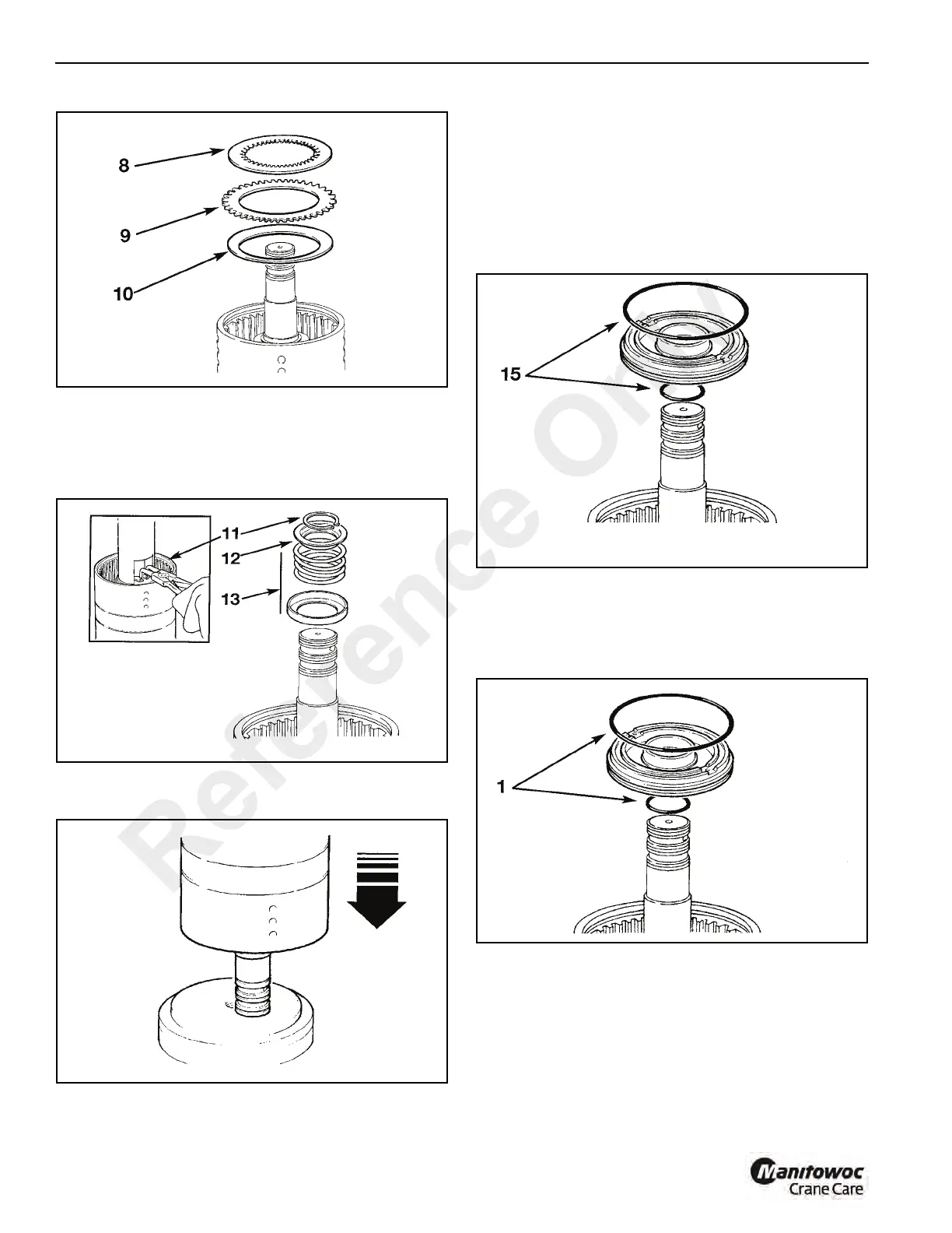
11. Position clutch assembly in press (Figure 7-78) to
compress piston spring 13 then remove circlip 11.
12. Lift off spring retaining plate 12.
13. Remove spring and oil baffle 13.
14. Knock the clutch shaft on a piece of aluminum (or wood)
to remove the piston.(See Figure 7-79)
NOTE: If the piston does not loosen when the clutch shaft
is knocked on aluminum, then hand pump air down
the shaft oil inlet hole.
15. Remove and discard piston and shaft O-rings
(Figure 7-80)
16. Repeat steps 2 thru 15 to disassemble the opposite
clutch. Note that a spacer is not fitted on the opposite
(Forward) clutch. Refer to step 4.
Assembly
1. Install new O-rings (1, Figure 7-81) onto the piston and
shaft, lubricate with oil then press piston fully into bore of
clutch housing.
2. Install the oil baffle and piston spring (2, Figure 7-82),
make sure the spring seats in the piston.
3. Install the spring retaining plate 3.
4. Compress spring 2 and secure with circlip 4.
Reference Only

 Loading...


