GROVE Published 10-21-2010, Control# 198-04 7-51
5540F/YB5515 SERVICE MANUAL TRANSMISSION AND TORQUE CONVERTER
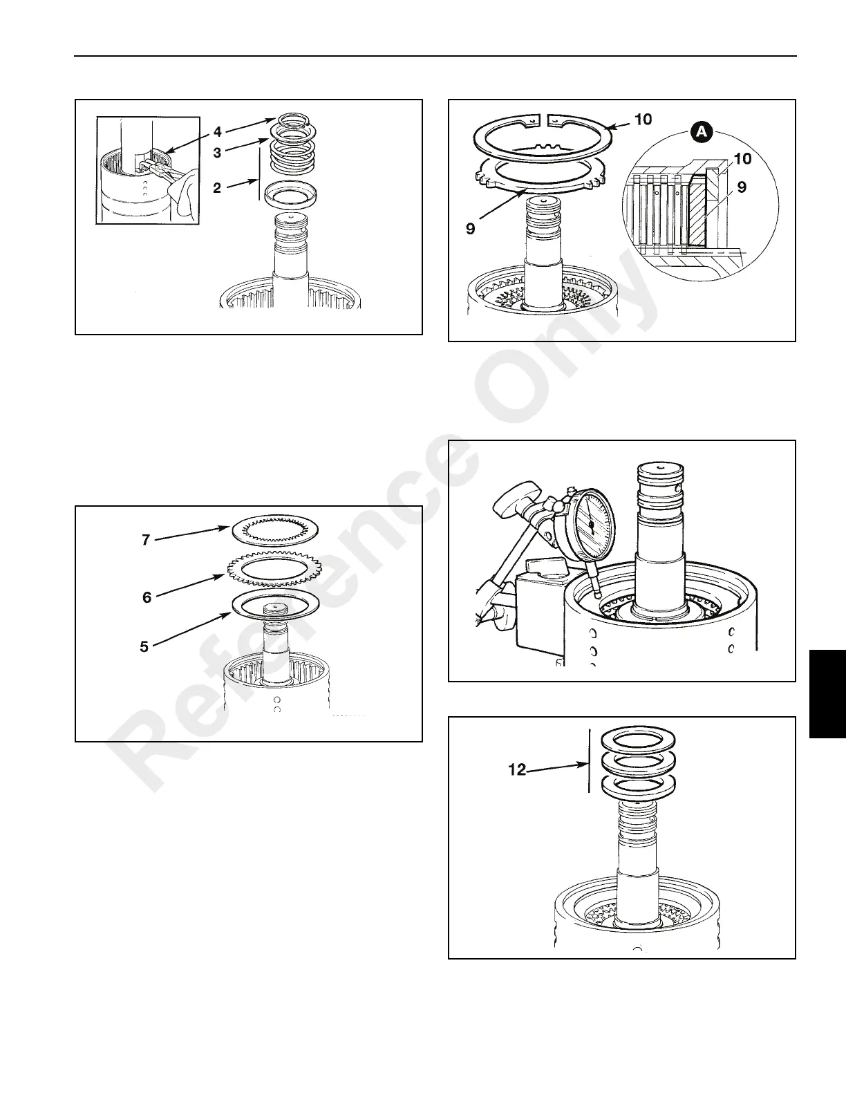
5. Install the disc spring assembly. (5, Figure 7-83). Install
the assembly so that the outer diameter curves away
from the clutch piston.
6. Firstly, install one counter plate 6.
7. Install one friction plate 7 followed by one steel counter
plate.
8. Continue installing alternating friction and plain steel
plates, finishing with a friction plate 7.
9. Install the pressure (end) plate (9, Figure 7-84). Make
sure that the chamfered face is fitted facing the clutch
pack as shown at A. Make sure that the prongs on the
pressure plate DO NOT locate in the large grooves in
the hub (the ones with drilled holes).
10. Install the clutch friction/counter plates retaining circlip
10. Using an air line blow air down the shaft oil inlet hole
and check the piston and clutch pack is free to operate
smoothly.
11. Using a dial test indicator, as shown (Figure 7-85),
measure the end float of the pressure (end) plate, which
should be 0.126 to 0.173 in (3.2 to 4.4 mm). Install shim
between the retaining circlip and pressure (end) plate to
correct end float inaccuracies.
12. Install thrust bearing and thrust washers.
13. Install gear and splined hub assembly (13, Figure 7-87).
Reference Only

 Loading...


