TRANSMISSION AND TORQUE CONVERTER 5540F/YB5515 SERVICE MANUAL
7-52 Published 10-21-2010, Control# 198-04
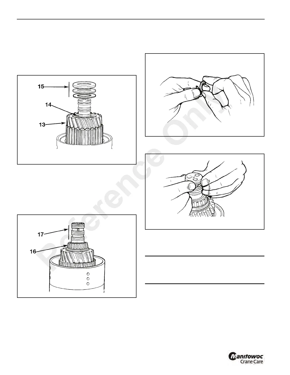
NOTE: Prior to fitting gear, align teeth of clutch plates
using a thin rod (screwdriver).
14. Install the spacer 14 followed by the needle roller
bearing.
NOTE: Ensure that the spacer is fitted first.
15. Install thrust bearing and thrust washers 15.
16. Coat the clutch end bearing (16, Figure 7-88) with Mobil
HP222 Grease and press the bearing onto shaft.
17. Install piston ring seals 17, refer to Piston Ring Seals -
Fitting Procedure.
18. Repeat steps 1 thru 16 for the opposite clutch. Note that
a spacer is not installed on the opposite (Forward)
clutch. Refer to step 14.
Piston Ring Seals - Fitting Procedure
1. Wind the PTFE piston ring seal around your finger as
shown (Figure 7-89), so that the seal forms a 'coil'.
2. Coat the seal with grease and then fit the seal to the
shaft. (Figure 7-90)
Make sure that the seal sits below or flush with the outer
diameter of the shaft. If necessary, use finger pressure as
shown to make the seal flush with the shaft.
CAUTION
If the seal is not set below or flush with the outer diameter
of the shaft, then the seal will 'cut' when the shaft is fitted
to its mating component.
Reference Only

 Loading...


