STRUCTURALS 5540F/YB5515 SERVICE MANUAL
11-48
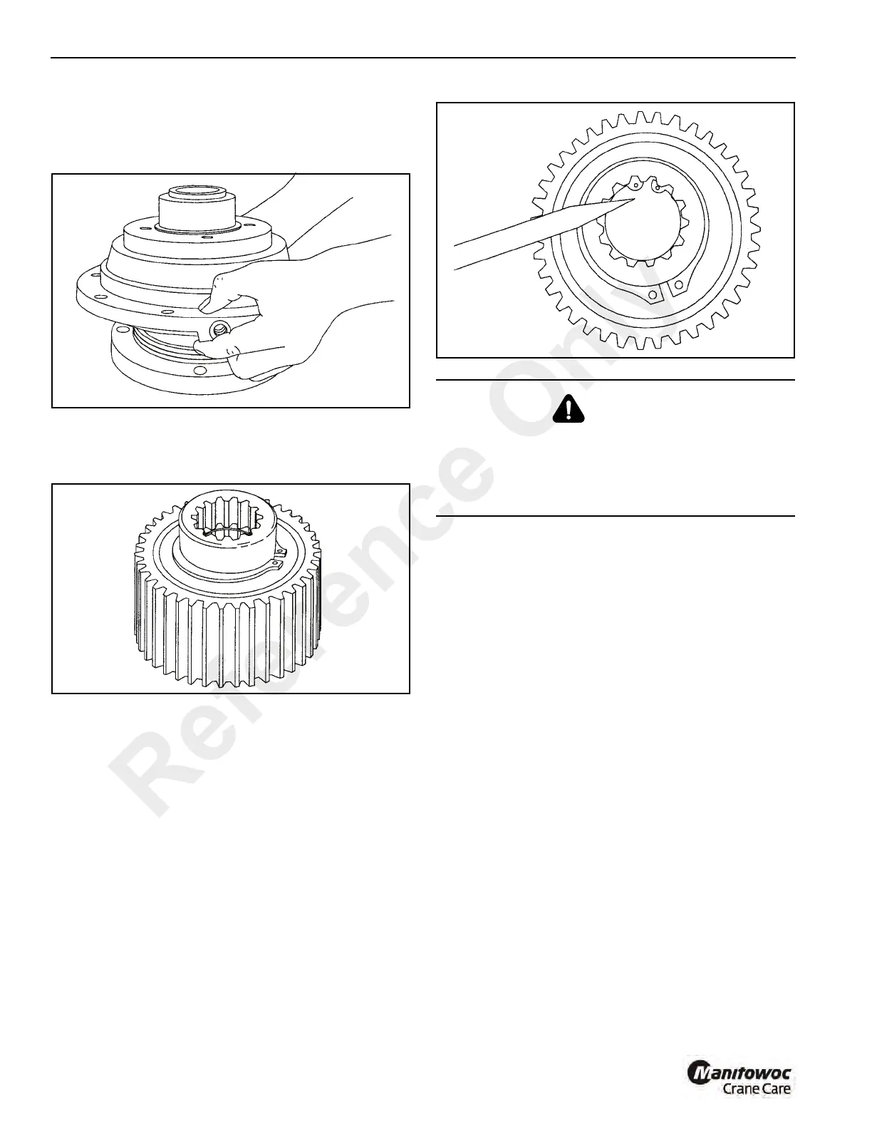
freewheeling direction to start it through the sprag
clutch. If the inner race will not go through the bushings,
the bushings have probably been damaged and should
be replaced.
6. Turn the assembly over with the snap ring down. Install
the second retainer and snap ring (Figure 11-118). Make
sure the snap ring is properly seated in the groove.
7. Figure 11-119 shows a completed clutch assembly.
Winch Tension Roller Subassembly Service
Disassembly
Use Figure 11-120 as a guide in disassembling the tension
roller assembly.
Assembly
1. When assembling the tension roller assembly use
washers (6, Figure 11-120) to center the roller assembly
between the drum flanges.
2. Tighten each eyebolt (9) to the dimension shown in
Figure 11-120.
3. Apply grease to shaft and I.D. of rollers. Rollers must
turn freely.
WARNING
Be certain the snap ring is seated in the groove in the
splined bore of the inner race.This snap ring will keep the
brake clutch assembly correctly positioned in the center of
the friction brake pack. Binding of the brake or brake
failure may occur if this snap ring is omitted.
Reference Only

 Loading...


