ENGINE AND ENGINE SYSTEMS 5540F/YB5515 SERVICE MANUAL
6-20 Published 10-21-2010, Control# 198-04
Turn ignition power OFF. Disconnect the ECM from the wire harness. Disconnect the MAP sensor and
TPS. Perform the following measurements:
1.4 If all other DBW tests check out, reconnect all sensors. Measure the voltage from DBW output to ground
while manually opening the foot throttle control. The voltage should move smoothly between low and high
speed. If the voltage has “dead spots” or spikes, replace the DBW device. If the voltage is within the range
and moves smooth, replace the ECM.
Code 32: System voltage too low.
This indicates the ECM is receiving a low battery voltage measurement. Verify the battery voltage measures
above 10 volts while the engine is running.
1. Measure the system (battery voltage) during normal operation. If it below 12.5 volts the charging system
should be diagnoses. Normal running battery voltage should read approximately 13 - 14.5 volts. If the battery
voltage is low, the charging system or machine wiring should be diagnosed.
2. Turn ignition power OFF, then disconnect the ECM. Turn ignition power ON. Measure the voltage between
pins ground (25 or 35) and switched power (11), and then the battery voltage. The two readings should be
with 0.5 volts unless the machine draws current for other functions. If any wires show considerable voltage
drop the wire should be inspected for damage or poor connections.
2.1 Measure the voltage between battery ground (-) and ECM pin 25. This voltage should be near 0.
2.2 Measure the voltage between battery ground (-) and ECM pin 35. The voltage should be near 0.
2.3 With ignition power still ON, measure voltage between ECM pin 11 and battery positive (+). This volt-
age should be near 0.
Code 41: MAP sensor system error.
The MAP sensor code can be set: if the map output wire is grounded to +5 volts, or if the MAP pressure does not
change between key on and engine run time. Verify:
1. MAP sensor is plugged in.
2. Vacuum hose to MAP sensor is connected properly with no leaks.
3. Disconnect MAP sensor electrical connector. Turn ignition power ON. Measure the voltage from pins A (BK/
YL) to C (RD/BU). This should read 4.75 - 5.25 volts. If it is outside of this range proceed with step 3.1.
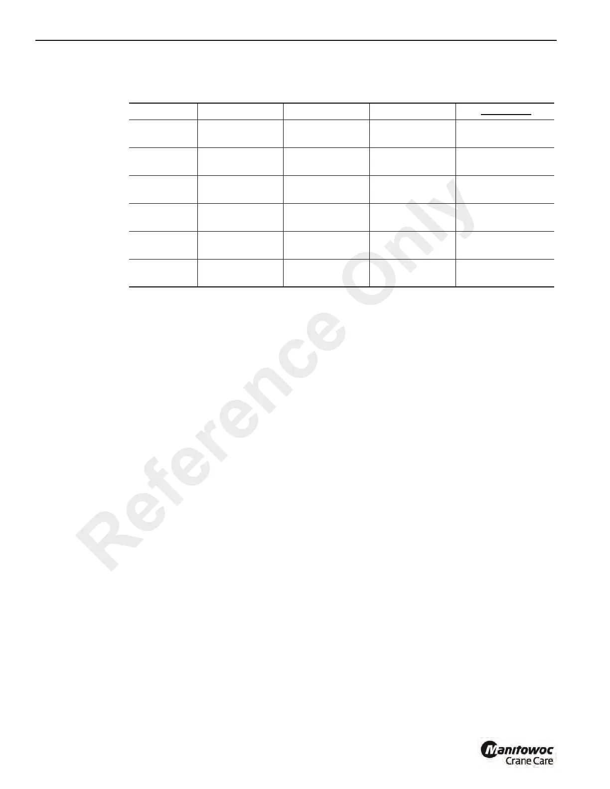
3.1 Perform the following measurements:
DBW Wiring Troubleshooting
Meter Mode From To Desired Result If Defective
Ohms ECM Harness 10
DBW GND
(BK/YL)
< 1 Ohm Ground wire is open
Ohms ECM Harness 40
DBW +5
(RD/BU)
< 1 Ohm 5 volt wire is open
Ohms ECM Harness 8
DBW output
(GN/YL)
< 1 Ohm
DBW signal wire is
open
Ohms ECM Harness 10 ECM Harness 40
Open or < 1000
Ohms if DBW pot
5 volt wire is shorted
to ground
Ohms ECM Harness 10 ECM Harness 18 Open
TPS signal shorted
to ground
Ohms ECM Harness 40 ECM Harness 18 Open
TPS signal shorted
to +5 volts
Reference Only
 Loading...


