4-43
Published 10/19/2017, Control # 618-00
GRT880 SERVICE MANUAL BOOM
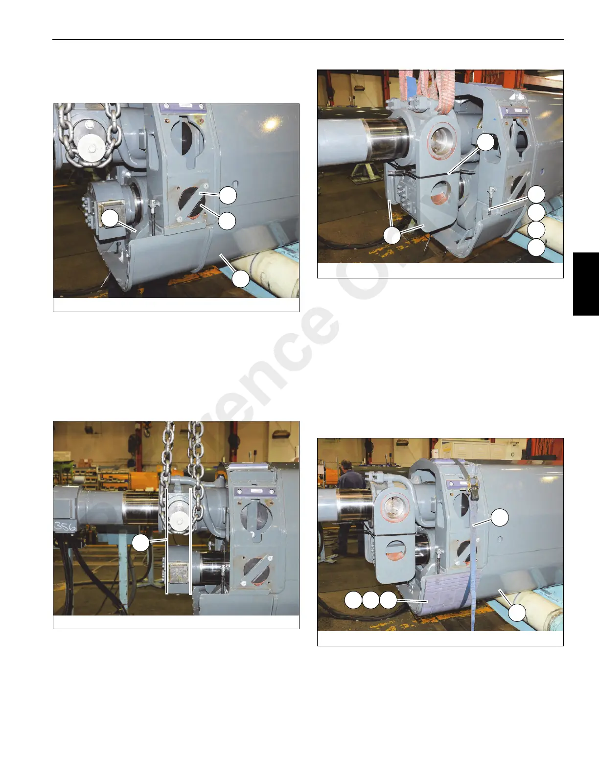
62. Simultaneously push cylinders #1 (502) and #2 (501)
into tele 2 (301) and tele 3 (401). Align holes in plates
(504, 508) with holes in tele 2 (301) (see Figure 4-107).
63. Apply anti-seize to pins (314) and install into left and
right sides of tele 2 (301). Secure each pin in place with
plate (322) and two bolts (346) (see Figure 4-107).
64. Vertically align trunnion lugs (L) of telescope cylinders
#1 (502) and #2 (501) with each other. Apply anti-seize
to all four trunnion lugs, then install plates (503) on left
and right sides of telescope cylinders #1 (502) and #2
(501) (see Figure 4-108 and Figure 4-109).
65. Install zip-tie (M) around the two plates (503) (see
Figure 4-109).
66. Install grease hose (303) and fittings (329, 330, 331) to
rear of tele 2 (301). Ensure grease fittings point outward
and hoses pass through holes in the gussets of tele 2
(301) (see Figure 4-109).
67. Install shims (317) and wear pads (304, 305) to bottom
(as oriented) of tele 2 (301). Align holes in shims with
pins on tele 2. Attach grease hose assemblies to rear
hole of each wear pad (304). Secure wear pads (304,
305) to tele 2 (301) using a ratchet strap (N) (see
Figure 4-110).
68. Position tele 1 (201) upside down on adequate supports
behind tele 2 (301).
FIGURE 4- 107
9044-54
504
301
314
322
FIGURE 4- 109
9044-56
503
M
330
331
329
303
FIGURE 4- 110
9044-57
305304
N
317
301
Reference Only

 Loading...


