8-3
GRT880 SERVICE MANUAL UNDERCARRIAGE
Published 10/19/2017, Control # 618-00
c. Clearance should be 25.4 mm (1.00 in) minimum, If
necessary, adjust the axle stop to provide
clearance.
3. Turn axle to extreme right and repeat step 2.
4. With the axles set at a 25.4 mm (1.00 in) clearance,
check the steer cylinders to see that they are not
bottomed out. To check the steer cylinders, remove the
pin at the rod end and apply pressure to move the
cylinder rod. The cylinder rod should travel a minimum of
3.0mm (0.12in).
Rear Steer Indicator Adjustment Procedure
1. Ensure the wheels are straight ahead.
NOTE: When performing rear steer indicator adjustment
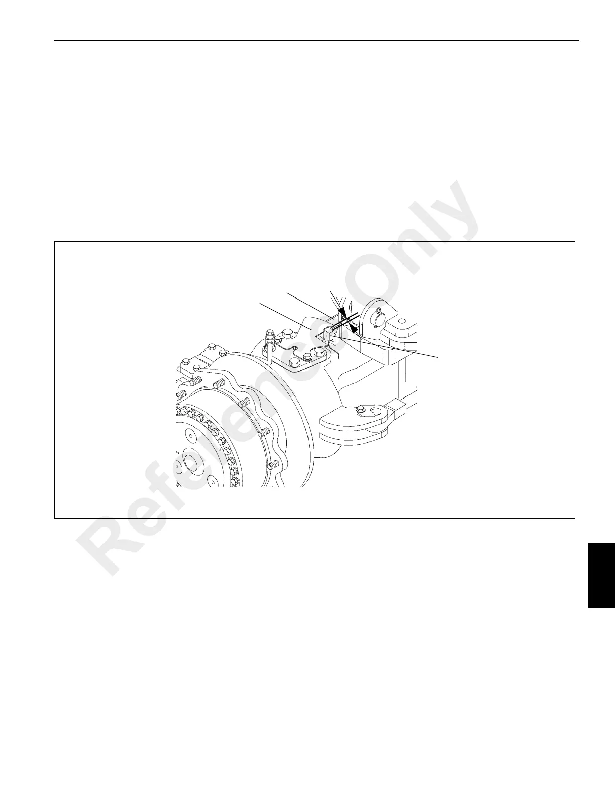
using the following steps, refer to Figure 8-1.
2. Slide the proximity switch through hole in rear steer
sensor bracket and secure with nuts and washers.
3. Set face of proximity switch 6 mm (0.24 in) from opening
in rear steer sensor plate. Tighten the fasteners.
4. Turn the rear wheels to verify proper operation. Rear
Wheels Not Centered Light in cab should be out when
rear wheels are centered and the sensor switch is
centered in the slot of the sensor plate.
6 mm (0.24 in)
Sensor Plate
Mounting Bracket
Sensor Switch
FIGURE 8-1
Reference Only

 Loading...


