Published 4-22-15, Control # 556-00 4-17
RT530E-2 SERVICE MANUAL BOOM
8. Using pins and cotter pins (1) (Figure 4-30), attach the
outer mid retract cables (2) laying in the bottom of the
inner mid to the lugs in the rear of the outer mid.
9. Slide the assembly into the inner mid being careful not to
damage any of the cables. As the sections slide together
pull the retract cables out the rear of the inner mid. Do
not fully slide together.
10. Lift up on the front of the assembly and install the bottom
front wear pads (1) in the pockets of the inner mid
(Figure 4-31).
11. Install inner mid front top (2) and bottom (3) side wear
pads with two screws each. On top left side attach
mounting angle (4) with bottom wear pad screw
(Figure 4-31).
12. Attach fly retract cable anchor plates (5) to front of inner
mid with two bolts each (6) (Figure 4-31).
13. Using four bolts and washers, attach the extend
synchronizing cable sheave assembly laying on top of
the outer mid to top front inside of the inner mid.
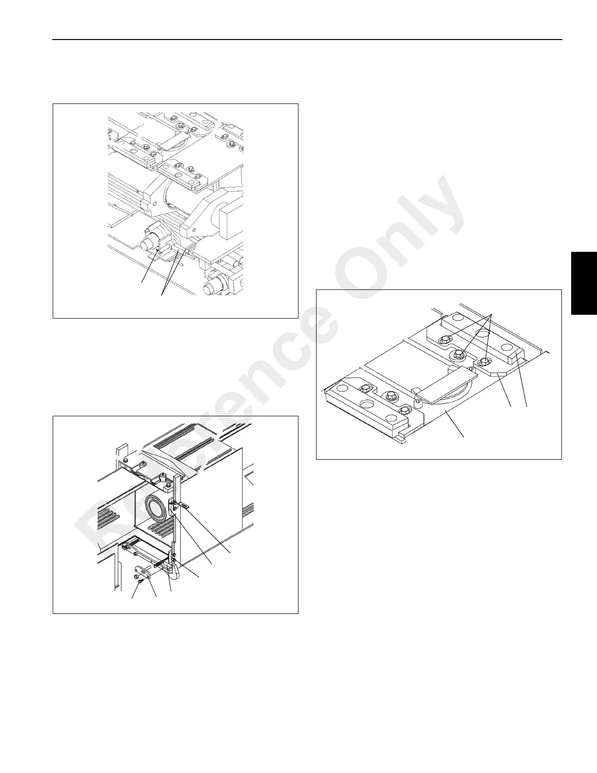
14. Through the top access hole in the inner mid, position
the two adjustable wear pads (2) on the top rear of the
outer mid (4). Install each wear pad holder (3) and
loosely install each with two capscrews and washers.
Install offset washers, capscrews, and washers (1)
(Figure 4-32). Using the offset washers, adjust the wear
pads such that the wear pads are within 1 mm (0.03 in)
from each side plate of the next outer section. Tighten
the offset washer and capscrews.
Connect Inner Mid Section
1. Route outer mid retract cables through the holes in the
bottom of the inner mid and pull them toward the front of
the assembly. Install the anchor plates on the cables
with cable locknuts. Be careful not to tangle cables.
2. While continuing to slide together, route extend cable
sled adjusting bolts through mounting holes in rear of
inner mid. Install nuts on the bolts.
3. Align the cylinder inner rod (1) mounting holes with the
tabs and holes in the rear of the inner mid and secure
with two capscrews and washers (2) (Figure 4-33).
Reference Only
 Loading...


