HOIST AND COUNTERWEIGHT RT530E-2 SERVICE MANUAL
5-8 Published 4-22-15, Control # 556-00
Procedure
The hoist mounting location will determine the alignment
procedure used. Shift one side of the hoist back or forward to
align the hoist with the boom sheave for cranes that have the
hoist mounted either directly to the boom or on a mount
attached to the boom. It may be necessary to shim under
one side of the hoist to make it level.
The hoist must be checked in two directions, one at 0 degree
and the other is above 45 degrees boom angle on any crane
that the hoist is not mounted directly to the boom, stationary
mounted.
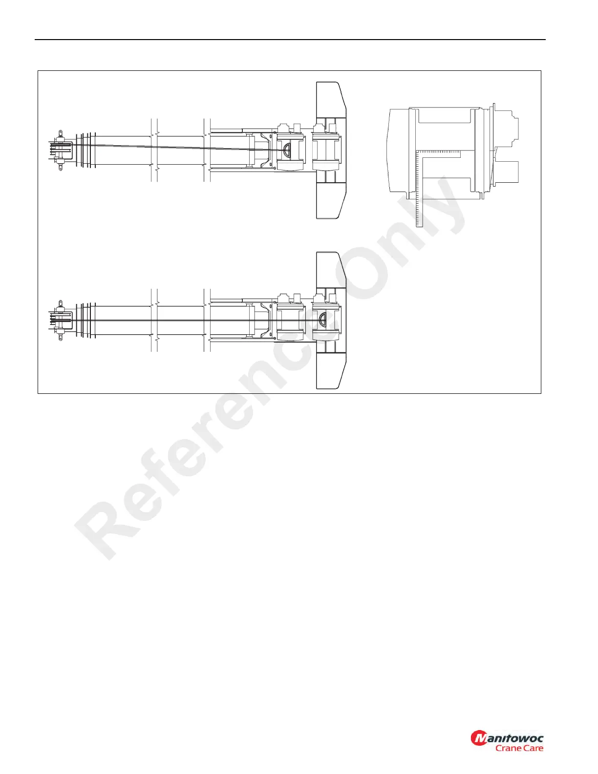
Check the hoist at 0 degree to see if the hoist is aligned to
the boom nose sheave. The main hoist is aligned to the right
hand sheave and the auxiliary hoist is aligned to the center
sheave (Figure 5-4)
NOTE: The hoist cable will have gaps in it during spooling
if the alignment is not correct.
NOTE: The hoist is not level if the cable is piling up on one
side of the drum.
1. The boom must be extended one half of full extension on
all hoist alignments. This length is used because when
the main hoist cable is positioned on the top right hand
boom nose sheave, the cable must leave the center of
the drum at a 90 degree angle. The boom has the ability
to extend, retract, and change the angle of departure
from the drum. Extend the boom half way to provide a
center point of adjustment to check the fleet angle of the
cable.
2. All the cable must be removed from the hoist drum to
check the fleet angle. Using mason cord or cat gut
fishing line you will be able to pull the line tight to make
an accurate measurement of the fleet angle. Find the
centerline of the hoist drum by using a square and
drawing a line horizontal on the drum. Put a line vertical
to the horizontal line in the absolute center of the drum
by using a tape measure. With the boom at 0 degree, tie
the line tight to the boom nose and have it in the center
of the right hand boom nose sheave.
NOTE: If this special equipment is not available, sufficient
accuracy in locating a centerline may be obtained
by using a steel square against the machine’s inner
surfaces of both flanges. It is advisable to avoid
using any cast surfaces in this procedure unless a
check from both flanges indicates that the resultant
line is straight.
3. Tie the line around the hoist drum so that the line is very
tight and the line is crossing the absolute center of the
drum at the centerline mark you put on the drum.
LOCATING CENTERLINE WITH
SQUARE
MAIN HOIST IS ALIGNED TO THE RIGHT HAND
SHEAVE
AUXILIARY HOIST IS ALIGNED TO THE CENTER
SHEAVE
FIGURE 5-4
6019
Reference Only
 Loading...


