Published 01-15-2016, Control # 526-01 3-21
RT540E OPERATOR MANUAL OPERATING CONTROLS AND PROCEDURES
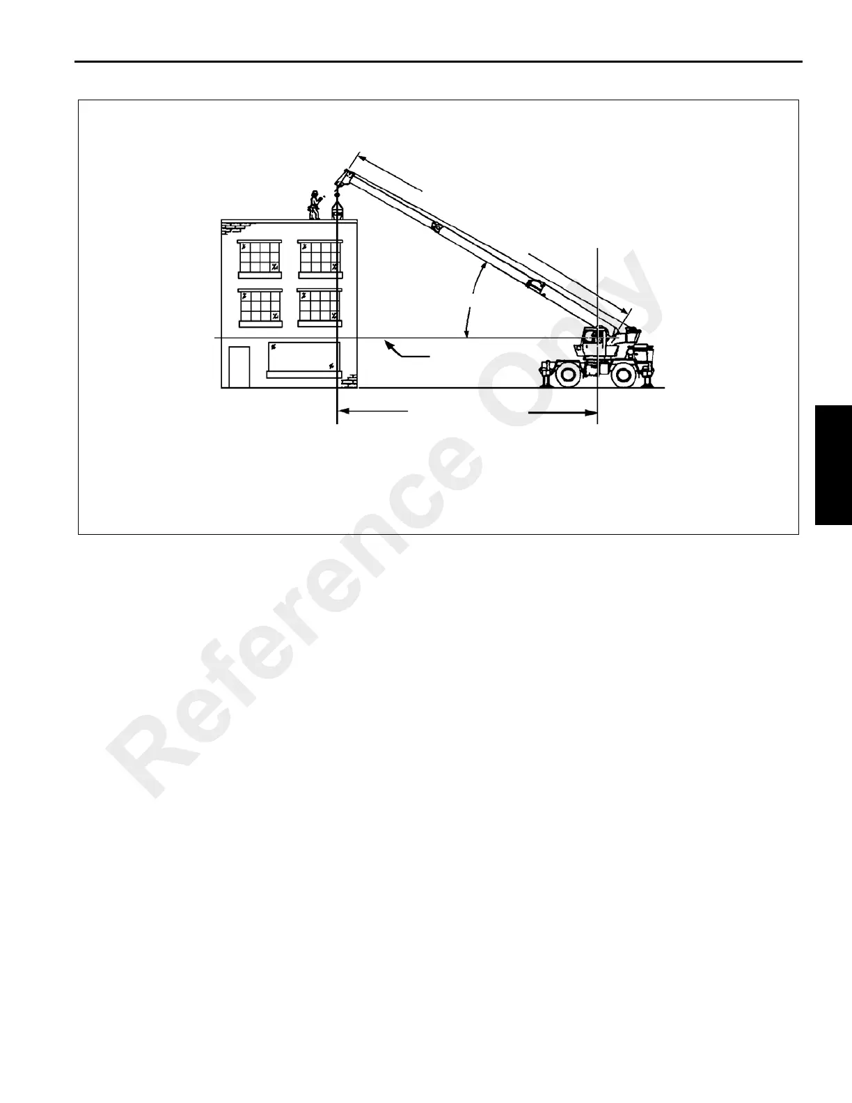
Another important section is the range diagram. The range
diagram shows the operating radius and tip height that can
be achieved at a given boom length and angle. If the
operator knows the radius and tip height required for a
specific lift, the angle and boom length can quickly be
determined from the range diagram. Or if he knows the boom
length and angle, he can quickly determine the tip height and
operating radius.
A lifting diagram is included for over-side, over-rear, and
over-front lifting areas. The lifting area diagram shows that
the locations of the outrigger jack cylinders in the full
extended position are used to mark the boundaries of the
lifting areas.
Another section contains notes for lifting capacities. Be sure
to read and understand all notes concerning lifting
capacities.
The load chart also gives weight reductions for Manitowoc/
Grove load handling devices such as hookblocks, overhaul
balls, boom extension sections, etc., which must be
considered as part of the load. The weight of any other load
handling devices such as chains, slings, or spreader bars
must also be added to the weight of the load.
NOTE: The information in the following paragraph is an
example of how to compute a lift. The numbers
used in the example may not coincide with the load
chart in the crane cab.
Problem: A concrete beam weighing 2268 kg (5000 lb)
needs to be lifted to a height of 9.1 m (30 ft) at a radius of
15.2 m (50 ft) (maximum). The range diagram indicates the
boom must be extended to 18.9 m (62 ft) in order to reach a
height of 9.1 m (30 ft) at a radius of 15.2 m (50 ft).
First we need to check the crane for load handling devices.
In our example, the crane is equipped with a auxiliary boom
nose (rooster sheave) and a five ton overhaul ball. The
rooster sheave is 50 kg (110 lb), and the overhaul ball is
78 kg (172 lb) for a total of 128 kg (282 lb). The lift requires
slings and spreader bars weighing 159 kg (350 lb) which
makes the total weight for the load handling devices 286 kg
(632 lb).
A check of the load chart for a 15.2 m (50 ft) radius and
19.5 m (64 ft) of boom length shows a capacity of 3601 kg
(7940 lb) on outriggers over-front and 4970 lb on outriggers
360 degrees. We subtract the load handling weight of 632 lb
from the load capacity of 3601 kg (7940 lb) and 2254 kg
(4970 lb). The result is a weight capacity of 3315 kg
(7308 lb) over-the-front and 1968 kg (4338 lb) for 360
degrees. We are constricted in making the lift over-front only
and the boom angle will be about 29 degrees.
Proper Leveling of the Crane
ASME B30.5 specifies that if a crane is not level within 1% of
grade, the allowable capacities must be reduced. Therefore,
whether lifting on rubber or outriggers, it is essential that the
FIGURE 3-10
OPERATING RADIUS
HORIZONTAL
BOOM ANGLE
M
A
I
N
B
O
O
M
L
E
N
G
T
H
AXIS OF ROTATION
4605
TERMS TO KNOW
Reference Only