SET-UP AND INSTALLATION PROCEDURES RT540E OPERATOR MANUAL
4-12 Published 01-15-2016, Control # 526-01
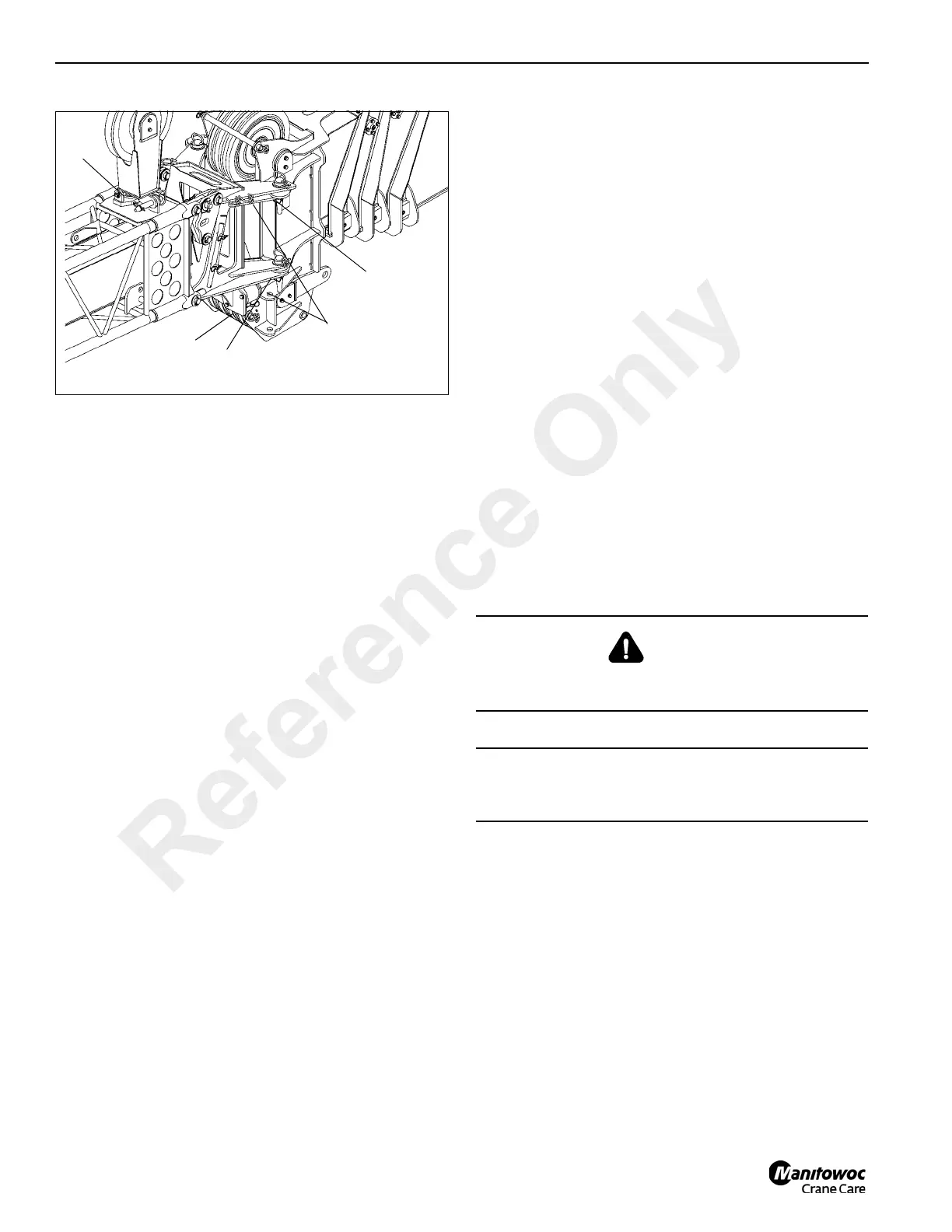
10. Extend the boom extension alignment jack (7) until the
lower left side boom nose and boom extension adapter
lugs are aligned.
11. Install the bottom left side attachment pin (8) and
retainer clip into the lower anchor and attachment fittings
of the boom nose.
12. Connect RCL cables:
a. Remove cable from boom extension.
b. Remove dummy plug from junction box on the boom
nose.
c. Install cable end connector from the boom
extension where dummy plug was removed
13. Release pressure on the boom extension alignment jack
(7). (Figure 4-13)
14. Install the Mast Assembly (9) in the upright position
using the locking pin.
15. Reeve the hoist cable. Refer to Cable Reeving in this
section.
Stowing
1. With crane set up on outriggers, fully retract the boom
and swing to over-the-front.
2. Lower the boom to minimum elevation.
3. Remove the cable retainer pin from the boom extension
tip and the mast assembly. Remove the hoist cable from
the sheaves. Install the cable retainer pins.
4. Remove the mast assembly retainer pin and the pin
securing the mast assembly in the upright position (9).
(Figure 4-13) Lay the mast assembly over to the stowed
position. Insert the pins securing the mast to the base
section.
5. Attach a length of rope to the boom extension tip.
6. Disconnect RCL cable:
a. Remove connector from junction box on boom
nose.
b. Install dummy plug in junction box.
c. Route cable to and attach to boom extension
7. Raise the boom to horizontal.
8. Extend the boom approximately 51 to 64 cm (20 to 25”).
Make certain that the boom extension stowage lugs will
line up in front of the guide pins (3) (Figure 4-12) and
ramp (4) (Figure 4-10) on the stowage brackets when
the boom extension is positioned to the side of the
boom.
9. Ensure the hitch pin (3) (Figure 4-10) and clip pin are
removed from the rear stowage bracket.
10. Extend the boom extension alignment jack (7) (Figure 4-
13) until the bottom left side attachment pin (8) is free.
Remove the bottom left side boom extension clip pin and
attachment pin.
11. Release pressure on the boom extension alignment
jack. Completely retract the jack.
12. Remove the top left side attachment pin (6) and clip pin
from the upper anchor and attachment fittings of the
boom nose.
13. Using the rope attached to the tip of the boom extension,
manually swing the extension to the side of the boom.
14. Align the stowage lugs on the boom extension with the
guide pins and ramp on the stowage brackets (Figure 4-
10) and (Figure 4-12) and fully retract the boom.
15. Install the hitch pin (2) Figure 4-10 and clip pin securing
the boom extension to the rear stowage bracket.
16. Remove the attachment pins (1) and clip pins from the
anchor and attachment fittings on the right side of the
boom nose (Figure 4-9) and stow them in the base of the
boom extension. Stow left side attachment pins and clips
in outside attachment fitting on swingaway.
DANGER
When stowing the boom extension, ensure that all
personnel and equipment are kept clear of the swing path.
CAUTION
Do not allow the boom extension to slam into the stowage
bracket when swinging into the stowed position.
Reference Only
 Loading...


