OPERATING CONTROLS AND PROCEDURES RT540E OPERATOR MANUAL
3-40 Published 01-15-2016, Control # 526-01
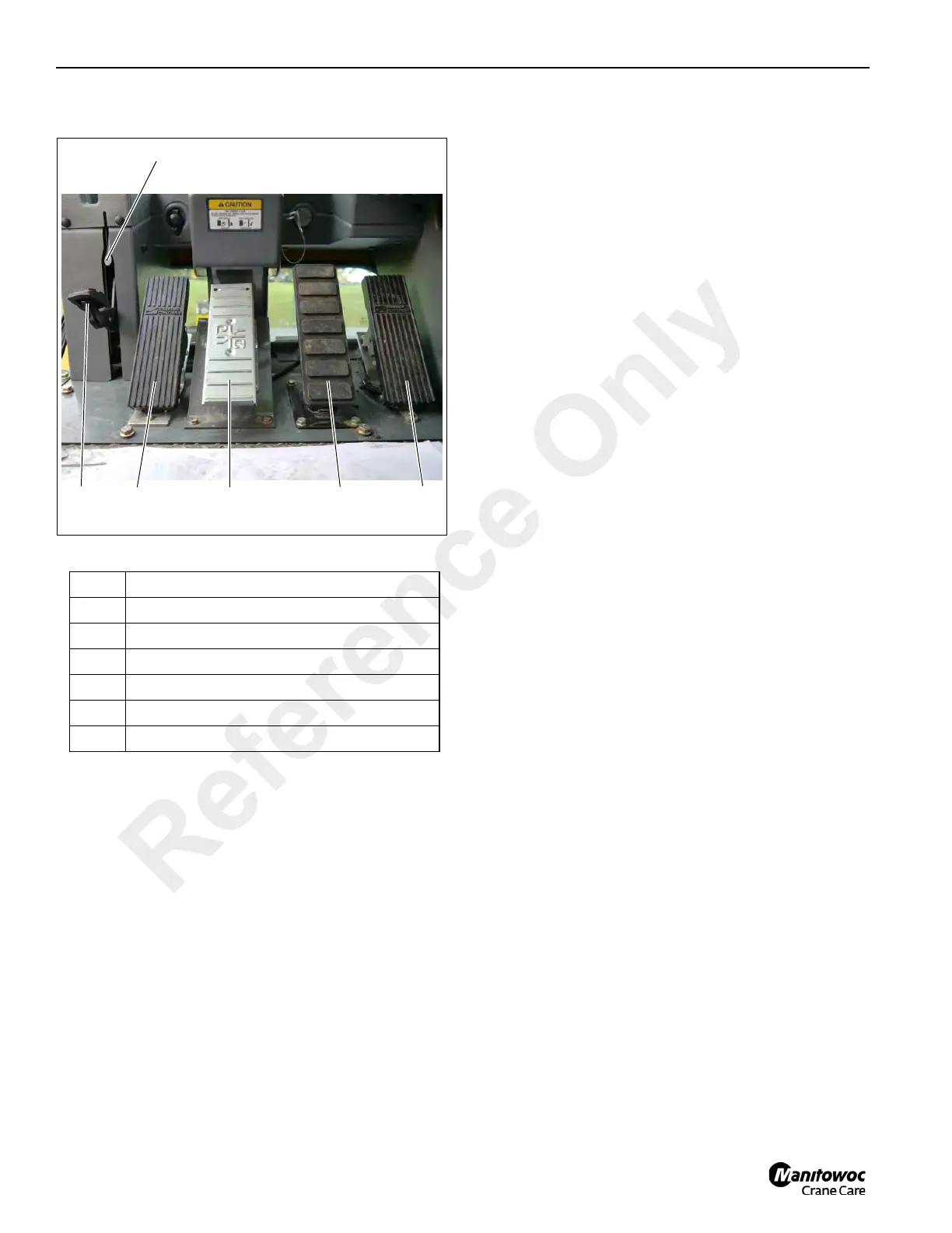
FOOT PEDAL CONTROLS
Figure 3-16 Item Numbers
360° Swing Lock Pedal
The 360° Swing Lock Pedal (1) (Figure 3-16) is located on
the left side of the crane cab floor. The pedal is used to
activate the swing lock to prevent the superstructure from
turning. To release the swing lock, pull up on the 360° Swing
Lock Release Lever (2).
Swing Brake Pedal
The Swing Brake Pedal (3) (Figure 3-16) is located on the
left side of the cab floor. The swing brake pedal is used to
actuate the swing brake to slow or stop swing motion.
Braking is proportional to pedal depression. With the pedal
not depressed and the swing brake control valve
disengaged, hydraulic pressure is applied to the brake,
overcoming spring pressure and releasing the brake.
Depressing the pedal actuates a swing power brake valve to
apply pressure to the brake assembly. This pressure aids the
spring pressure to overcome the hydraulic pressure being
applied to the brake release circuit and applies the spring
brake according to the pressure from the swing power brake
valve.
Telescope Control Pedal (Optional)
The Telescope Control Pedal (4) (Figure 3-16) is supplied
when the crane is equipped with an auxiliary hoist, is located
in the middle of the cab floor. Pushing forward on the top of
the pedal will extend the boom and pushing down on the
bottom of the pedal will retract the boom.
Service Brake Pedal
The Service Brake Pedal (5) (Figure 3-16) is the second
pedal from the right on the cab floor. Depressing the pedal
controls the application of the service brakes.
Foot Throttle Pedal
The Foot Throttle Pedal (6) (Figure 3-16) is located on the
right side of the floor. It is used to control engine RPM which
increases or decreases proportionately with the amount of
foot pressure applied to the pedal. The pedal is electrically
connected to the superstructure control module which sends
the signal to the engine ECM via the J1939 data link.
MISCELLANEOUS CONTROLS AND
INDICATORS
Fuse Panel
The fuse panel (1) (Figure 3-17) is located behind the cab
seat on the cab fuse and relay panel assembly. It contains up
to 20 fuses that protect the various electrical components of
the crane.
Buzzer
The buzzer in the display sounds when the following
conditions exist:
• Engine Alarms
• Emergency Stop Switch activated
• Low brake pressure
• High hydraulic oil temperature
• High transmission oil temperature
• Low steer pressure condition (for CE units)
• Hoist third wrap condition (for CE units)
• Anti Two-Block alarm
• Engine compartment protection program
Item Description
1 360° Swing Lock Pedal
2 360° Swing Lock Release Lever
3 Swing Brake Pedal
4 Telescope Control Foot Pedal (Optional)
5 Service Brake Pedal
6 Foot Throttle Pedal
Reference Only