OPERATING CONTROLS AND PROCEDURES RT540E OPERATOR MANUAL
3-14 Published 01-15-2016, Control # 526-01
4. Turn the ignition switch to start (far right position) and
release immediately when the engine starts. Do not
push or hold the throttle down. The ECM will
automatically provide the proper amount of fuel to start
the engine.
5. Allow the engine to warm up for about five minutes
before applying a load. Do not race the engine for a
faster warm up.
Idling The Engine
Idling the engine unnecessarily for long periods of time
wastes fuel and fouls injector nozzles. Unburned fuel causes
carbon formation; oil dilution; formation of lacquer or gummy
deposits on the valves, pistons and rings; and rapid
accumulation of sludge in the engine.
NOTE: When prolonged engine idling is necessary,
maintain at least 800 rpm.
Racing The Engine
DO NOT race the engine during the warm-up period or
operate the engine beyond governed speed (as might occur
in downhill operation or downshifting). Engine bearings,
pistons, and valves may be damaged if these precautions
are not taken.
Shutdown Procedure
1. Allow the engine to run at fast idle speed for about five
minutes to avoid high internal heat rise and allow for
heat dissipation.
2. Position the ignition switch to off (vertical position).
3. Drain the fuel filter-water separator.
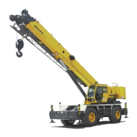
Battery Disconnect
The battery disconnect switch is located in the battery box on
the left side of the crane. To disconnect the batteries, turn the
battery disconnect switch to OFF. Turn the switch to ON to
connect the batteries.
Crane Travel Operation
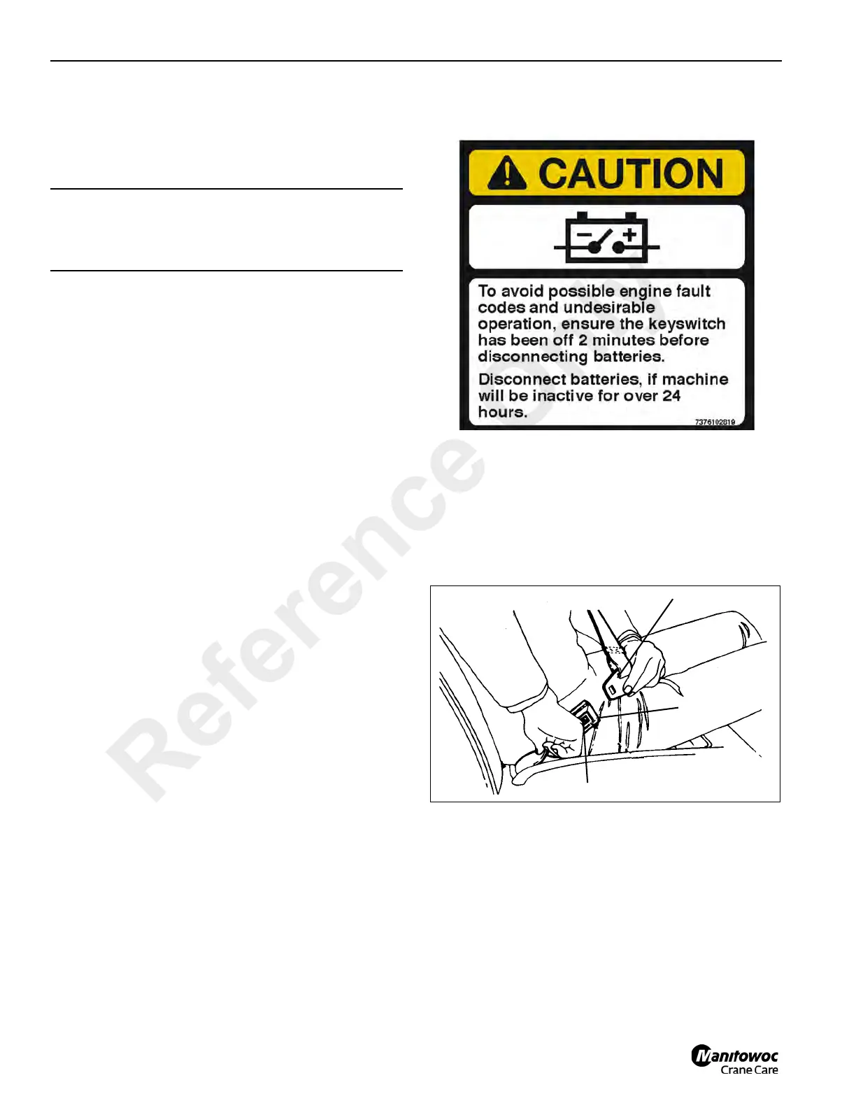
Seat Belts
1. Before fastening a seat belt, always adjust the driver’s
seat to the position in which you will drive.
2. Pull the belt across your lap and push the latch plate into
the buckle until it clicks (Figure 3-8).
3. To reduce the risk of sliding under the belt during a
collision, position the belt across your lap as low on your
hips as possible and pull it toward the door to a snug fit.
CAUTION
If oil pressure and/or temperature indicator(s) do not
display the proper readings, shut down engine and
correct malfunction.
Latch Plate
Buckle
Push Button
FIGURE 3-8
Reference Only