OPERATING CONTROLS AND PROCEDURES RT540E OPERATOR MANUAL
3-2 Published 01-15-2016, Control # 526-01
Service Brake Pedal . . . . . . . . . . . . . . . . . . . . . . 3-40
Foot Throttle Pedal . . . . . . . . . . . . . . . . . . . . . . . 3-40
Miscellaneous Controls and Indicators . . . . . . . 3-40
Fuse Panel . . . . . . . . . . . . . . . . . . . . . . . . . . . . . 3-40
Buzzer . . . . . . . . . . . . . . . . . . . . . . . . . . . . . . . . . 3-40
RCL Emergency Override Switch
(Non-CE Certified Cranes) . . . . . . . . . . . . . . . . . 3-41
RCL Emergency Override Switch and Indicator
(CE Certified Cranes). . . . . . . . . . . . . . . . . . . . . . 3-41
RCL Internal Light Bar (Optional). . . . . . . . . . . . . 3-42
Strobe Light or Beacon (Optional) . . . . . . . . . . . . 3-42
Backup Alarm. . . . . . . . . . . . . . . . . . . . . . . . . . . . 3-42
Emergency Exit . . . . . . . . . . . . . . . . . . . . . . . . . . 3-42
Appendix A: Crane Control System (CCS) Symbols
and Icons . . . . . . . . . . . . . . . . . . . . . . . . . . . . . . . 3-43
CONTROLS AND INDICATORS
The engine is electronically controlled by the Electronic
Control Module (ECM); it is the control center of the entire
engine system. The ECM processes all of the inputs and
sends commands to the fuel systems as well as vehicle and
engine control devices. This Operator Manual does not
include information on the engine ECM, however a separate
manual as prepared in detail by the engine manufacturer is
shipped with the crane from the factory.
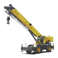
All the controls and indicators to operate and monitor crane
functions are found inside the crane cab (Figure 3-1) and
include the following:
1. Foot Pedals
2. Turntable Swing Pin Lock Control
3. Seat Joystick and Armrest Controls
4. CCS and RCL Display Panels
5. Steering Column
6. Overhead Control Panels
Steering column
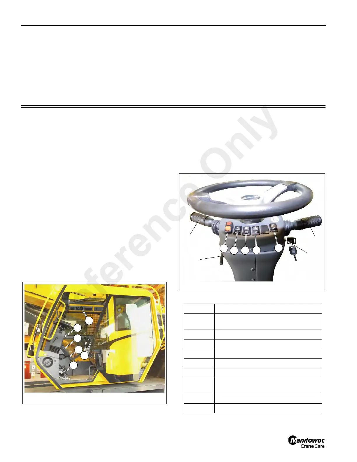
The steering column assembly (Figure 3-2) is a pedestal
style tilt and telescoping steering column. It has the ability to
tilt rearward 30° or be raised vertically approximately 60 mm
(2.3 in). It also includes the ignition switch and other control
switches (Figure 3-2).
Figure 3-2 Item Numbers+
Item Description
1
Turn Signal Lever and Windshield Wiper/
Washer/Horn Controls
2 Steering Column Tilt Lever
3 Park Brake Control Switch
4 Headlights Switch
5 Drive Axle Selector Switch
6 Hazard Lights Switch
7
Engine Speed Increment/Decrement
Switch (RPM)
8 Ignition Switch
9 Transmission Shift Lever
Reference Only