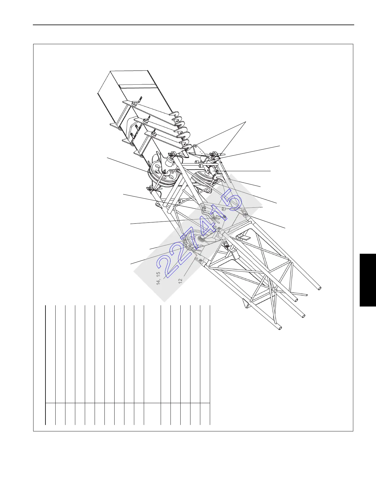
Offset shown at 25 degrees. To obtain 45 degree offset, remove pin (item
12) and stow in lug. Cranes with s/n 220720, 220721and 220722 can only
be offset to a maximum of 25 degrees. The offset links for these cranes
are of different design.
FIGURE 4-14 continued
Item Description
1 Boom Nose Upper Sheaves
2 Mast Assembly
3 Offset Links
4 Offset Pivot Points
5 Offset Link Pins Stowage Lugs
6 Boom Nose Lower Sheaves
7 Jack Handle
8 Alignment Jack
9 Swingaway Attachment Pins
10
Swingaway Attachment Pin
Stowage Lugs
11 Offset Link Pins
12 Zero Degree Offset Hole
13 Roller
14 Clevis Pin
15 Hitch Pin Clip
12
2
11
3
4
5
6
7
8
10
9
1
13
14, 15
 Loading...