3-29
RT600E OPERATOR MANUAL OPERATING CONTROLS AND PROCEDURES
Published 05-02-2018 Control # 088-10
5. Using the bubble level indicator mounting screws, adjust
the bubble level indicator to show level.
Using Your Load Chart
NOTE: One of the most important tools of every Grove
crane is the load chart found in the crane operator’s
cab.
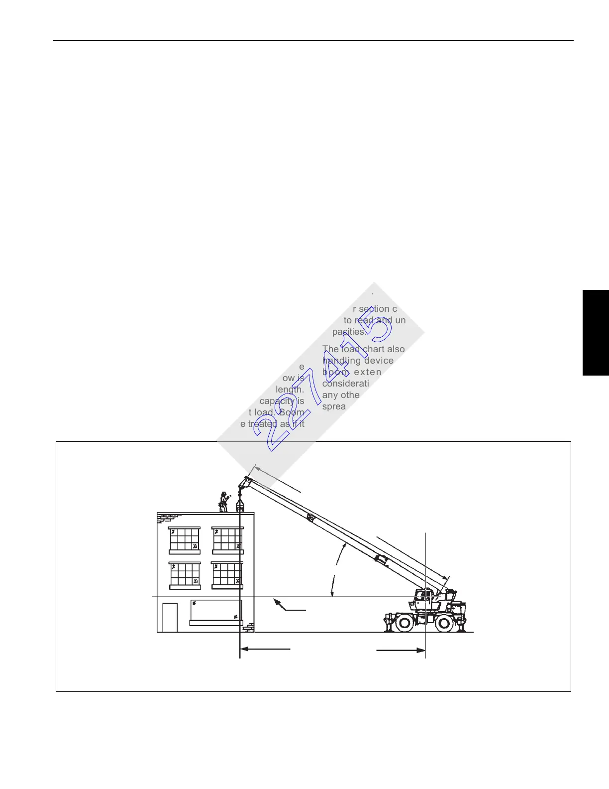
NOTE: Refer to Figure 3-6 for terms to know in
determining lifting capacities.
The load chart contains a large amount of information, which
must be thoroughly understood by the operator.
The load chart contains four outrigger capacity charts: fully,
mid, and retracted outriggers main boom and boom
extension with full outriggers. In addition, the load chart
contains three on-rubber capacity charts: over front
stationary, 360° stationary, and pick and carry over front.
The capacity charts are divided into structural strength and
stability limits. This is shown by the bold line across the chart.
Capacities above the line are structural strength limits and
capacities below the line are stability limits.
The left column is the load radius, which is the distance from
the center of crane rotation to the load center of gravity. The
top row lists various boom lengths ranging from fully
retracted to fully extended with the swingaway jib. The
number at the intersection of the left column and top row is
the total load capacity for that load radius and boom length.
The number in parentheses below the total load capacity is
the required boom angle (in degrees) for that load. Boom
lengths between increments should always be treated as if it
were the next longer length. For example, if the actual boom
length is 50 ft and the chart shows boom lengths of 48 and
54 ft, use the load capacity shown in the 54 ft column.
Another important section is the range diagram. The range
diagram shows the operating radius and tip height that can
be achieved at a given boom length and angle. If the
operator knows the radius and tip height required for a
specific lift, the angle and boom length can be quickly
determined from the range diagram. Or, if the boom length
and angle are known, the tip height and operating radius can
be quickly determined.
A lifting diagram is included to describe over side, over rear,
and over front lifting areas. The lifting area diagram shows
that the locations of the outrigger jack cylinders in the full
extended position are used to mark the boundaries of the
lifting areas.
A boom extension capacity chart and notes are included to
list the capacities for the extension length, load radius, and
boom angle.
Another section contains the notes for lifting capacities. Be
sure to read and understand all the notes concerning lifting
capacities.
The load chart also gives weight reductions for Grove load
handling devices such as hook blocks, headache balls,
boom extensions, etc., which must be taken into
consideration as part of the load. Remember, the weight of
any other load handling devices such as chains, slings, or
spreader bars must be added to the weight of the load.
FIGURE 3-6
OPERATING RADIUS
HORIZONTAL
BOOM ANGLE
M
A
I
N
B
O
O
M
L
E
N
G
T
H
AXIS OF ROTATION
4605
227415