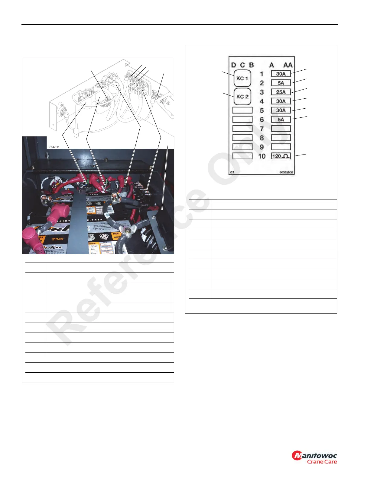
EasyManua.ls Logo

Manitowoc Grove RT765E-2 - Page 134

Manitowoc Grove RT765E-2
330 pages
Print Icon
To Next Page IconTo Next Page
To Previous Page IconTo Previous Page
Loading...
ELECTRICAL SYSTEM RT765E-2 SERVICE MANUAL
3-6
Published 9-04-2014, Control # 422-08
Ignition key switch is in the ACC and RUN positions.
ACC Relay #2 is not energized while in START position.
.
4
5
6
7
8
9
1
2
3
Item Description
1 Power Relay (K301)
2 Start Relay (K303)
3 Grid Heater Relay (K302)
4 250 Amp Fuse (F53)
5 100 Amp Fuse (F54)
6 100 Amp Fuse (F55)
7 100 Amp Fuse (F56)
8 100 Amp Fuse (F52)
9 250 Amp Fuse (F51)
10 Fuse and Relay Panel (see Figure 3-7)
FIGURE 3-6
10
FIGURE 3-7
5
6
7
4
3
2
1
Item Description
1 ECM, 30 Amp Fuse (F1)
2 Cranestar, 5 Amp Fuse (F2)
3 Carrier, Rear Module, 25 Amp Fuse (F3)
4 Carrier, Rear Module, 30 Amp Fuse (F4)
5 Carrier, Front Module, 30 Amp Fuse (F5)
6 Power Control Relay, 5 Amp Fuse (F6)
7 120 Ohm Resistor, Starter Lockout Circuit
8 Relay KC1, Power Control Relay
Relay KC2, Remote Crank Relay
7860
8
9
Reference Only

Table of Contents

Other manuals for Manitowoc Grove RT765E-2

Related product manuals