2-23
RT765E-2 SERVICE MANUAL HYDRAULIC SYSTEM
Published 9-04-2014, Control # 422-08
PRESSURE SETTING PROCEDURES
The following procedures should be used to properly check,
adjust and set the hydraulic system pressures.
The following equipment is required for checking the
hydraulic pressure settings.
• Pressure Gauge (1) three dial gauge 0-5000 psi (0-
34.5 MPa)
• Accumulator charging and gauging assembly for
3000 psi (20.7 MPa)
• ORFS reducers as required to attach work port hoses to
the gauge.
NOTE: When checking the directional control valve relief
settings, unless otherwise specified, start with the
engine at idle RPM and move the controller to its
fully stroked position. Then slowly accelerate the
engine to the specified RPM. Read gauge and
make adjustments to specified setting.
When checking the outrigger relief valve setting,
start with the engine at idle RPM and activate and
hold the extend or retract switch. Then slowly
accelerate the engine to the specified RPM. Read
gauge and make adjustment as required.
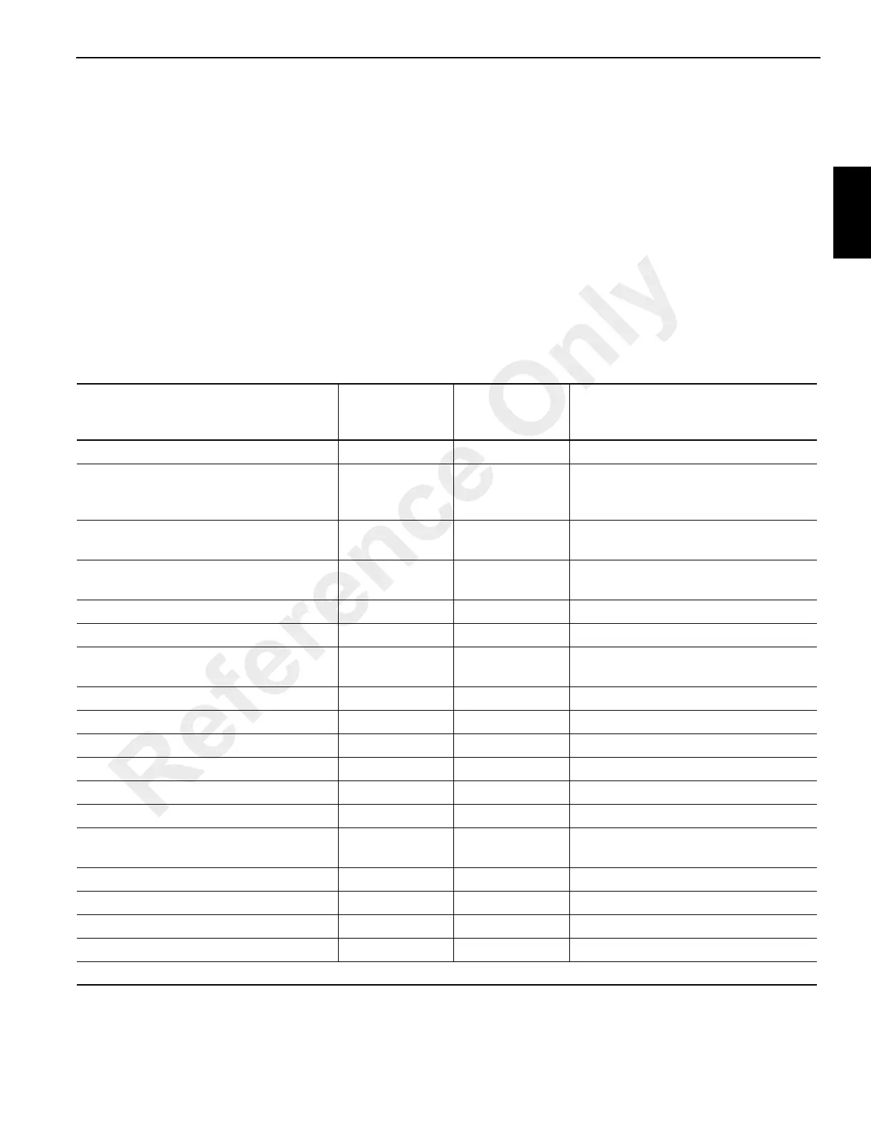
Table 2-2
Valve Pressure Setting Table
Valve To Be Set
Pressure
Setting
PSI (MPa)
Tolerance
PSI (MPa)
Adjustment Location
Load Sense Relief* 4000 (27.6) ±50 (±0.4) Main Control Valve Inlet Gauge Port
Lift Down Relief 2000 (13.8)
+700/-0
(+4.8/-0)
Telescope Retract Relief 3500 (24.1) ±50 (±0.4)
Main Control Valve Telescope Retract
Port
Telescope Extend Relief 2700 (18.6) ±50 (±0.4)
Main Control Valve Telescope Extend
Port
Hoist Raise 3500 (24.1) ±50 (±0.4) Main Control Valve Hoist Raise Port
Hoist Lower 3500 (24.1) ±50 (±0.4) Main Control Valve Hoist Lower Port
Pilot Pressure Supply
325 to 450
(2.2 to 3.1)
within listed
range only
Main Control Valve Inlet
Swing Brake Pilot Supply 250 (1.7) +50/-0 (+0.4/-0) Pressure Reducing Valve
Front Steer Relief Valve 2500 (17.2) ±50 (±0.4) Swing/Steer Control Valve
Swing “Left” Relief 2200 (15.2) ±50 (±0.4) Swing/Steer Control Valve
Swing “Right Relief 2200 (15.2) ±50 (±0.4) Swing/Steer Control Valve
Outrigger/Rear Steer Relief 2500 (17.2) ±50 (±0.4) Outrigger/Rear Steer Valve Inlet
Service Brake 3000 (20.7) ±50 (±0.4) Service Brake/CAC Fan Valve
Service Brake High Charge Limit 2320 (17.4)
+72/-145 (+0.5/
-1.0)
Dual Accumulator Charge Valve
Service Brake Low Charge Limit 1950 (13.5) ±145 (±1.0) Dual Accumulator Charge Valve
Accumulator Pre-Charge 900 (6.2) +50/-0 (+0.4/-0) Accumulator
Charge Air Cooler Fan Motor Relief 1000 (6.9) +50/-0 (+.4/-0) Service Brake/CAC Fan Valve
Counterweight Valve 1750 (12.07) ±50 (±0.4) Counterweight Valve
*This setting is for Boom Lift “UP” Circuit
Reference Only
 Loading...


