HYDRAULIC SYSTEM RT765E-2 SERVICE MANUAL
2-48
Published 9-04-2014, Control # 422-08
Maintenance
Removal
1. Tag and disconnect the electrical connectors to the
valve. Tape the lead ends.
2. Tag and disconnect the hydraulic lines to the valve. Cap
or plug the lines and ports.
3. Remove the capscrews, nuts, and washers securing the
valve to the frame. Remove the valve as a complete
assembly.
Installation
1. Install the integrated outrigger/rear steer valve to the
frame. Secure the valve with the flatwashers,
lockwashers, hex nuts and capscrews. Torque
capscrews; refer to Fasteners and Torque Values, page
1-16 for proper torque value.
2. Connect the hydraulic lines to the integrated outrigger/
rear steer valve as tagged during removal.
3. Connect the electrical connectors to the integrated
outrigger/rear steer valve as tagged during removal.
Functional Check
1. Cycle an outrigger cylinder several times. Verify the
cylinder extends and retracts properly.
2. Rear steer the crane to the left and to the right several
times. Verify the crane steers properly in both directions.
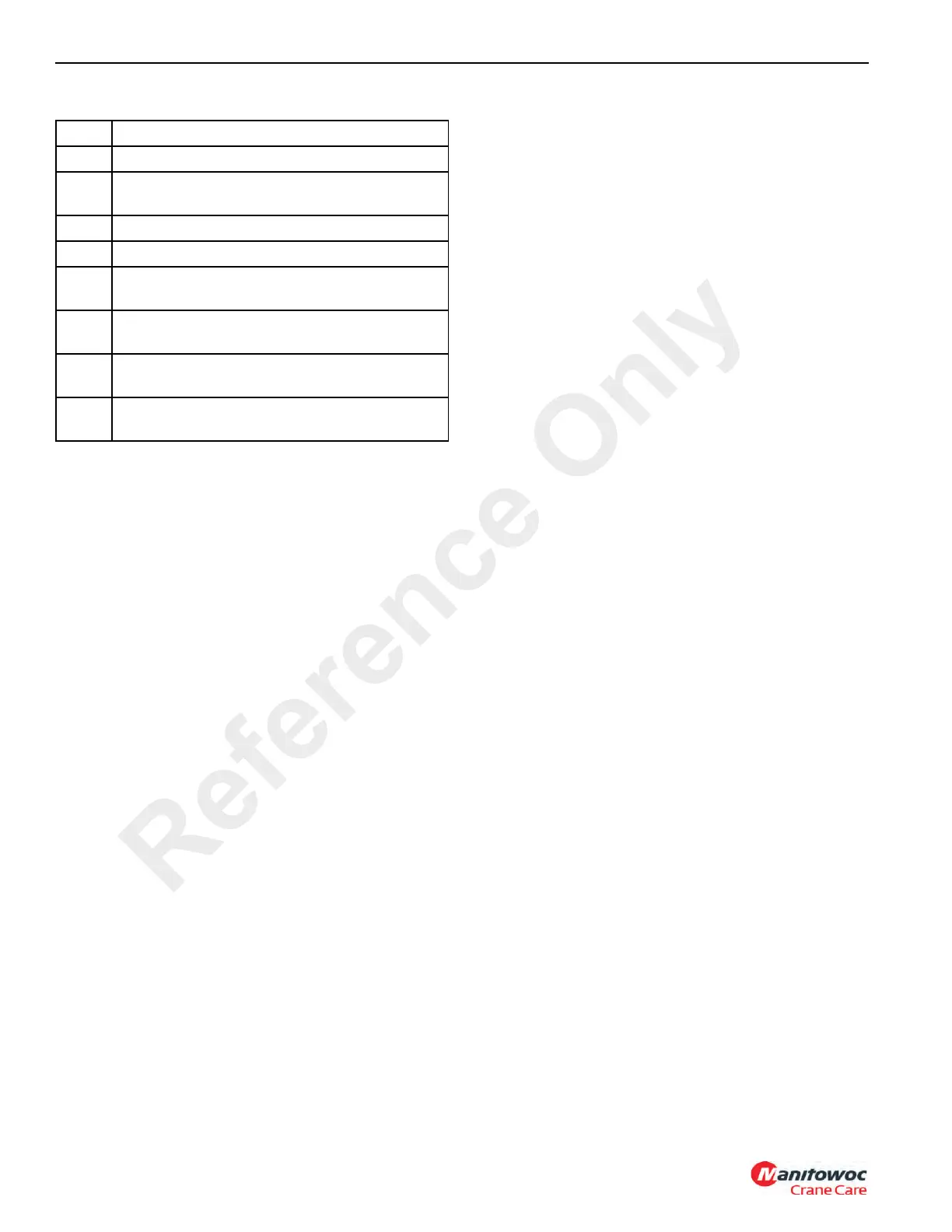
Item Description
1 Port T - Tank
2
Port P - Pressure from High Speed Boost
Selector Valve
3 Port GP - Gauge Port
4 Port OA - Solenoid Valve SV2 - Jack Cylinders
5
Port OB - Solenoid Valve SV1 - Extension
Cylinders
6
Port SA - Solenoid Valve SV5 - Rear Steer
Cylinders
7
Port SB - Solenoid Valve SV4 - Rear Steer
Cylinders
8
Solenoid Valve SV3 from High Speed Boost
Selector Valve
Reference Only
 Loading...


