HYDRAULIC SYSTEM RT765E-2 SERVICE MANUAL
2-24
Published 9-04-2014, Control # 422-08
Procedure A - Main Control Valve Reliefs
1. Install pressure check diagnostic quick disconnect with
gauge onto test nipple at main directional control valve
inlet gauge port Figure 2-7.
2. Completely extend lift cylinder (or cap hose from “A” port
to the lift cylinder), attempt to lift up with engine running
at full rpm. Adjust the load sense relief to 4000 psi ±50
(27.6 MPa ±0.4).
3. Remove pressure gauge.
4. Install pressure check diagnostic quick disconnect with
gauge onto test nipple at main directional control valve
load sense relief test port Figure 2-7.
Disconnect
Hoist Brake
Release
Line
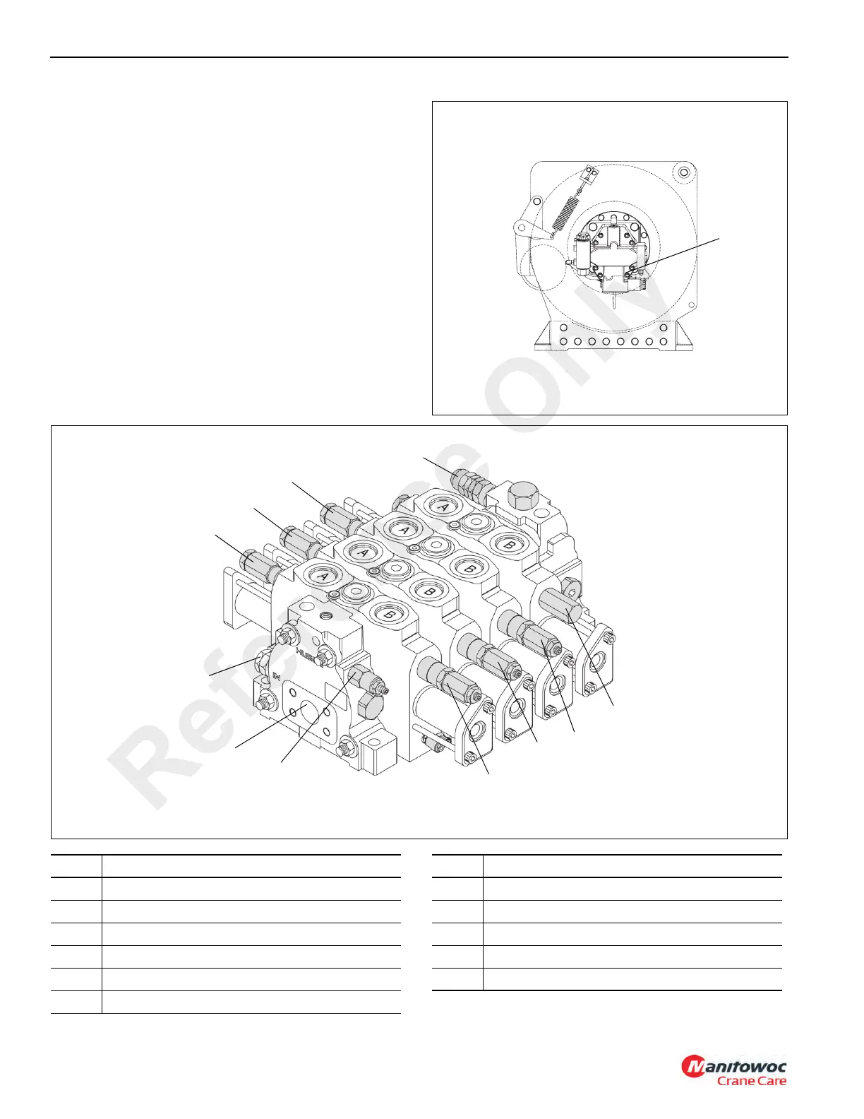
FIGURE 2-6
6659-1
Right Side View of Main Hoist
FIGURE 2-7
6468-1
8
7
1
9
10
6
5
4
3
2
11
Item Description
1 Auxiliary Hoist Down Port Relief
2 Main Hoist Down Port Relief
3 Load Sense Relief Test Port
4 Inlet Gauge Port
5 Pilot Supply Pressure Reducing Cartridge
6 Main Hoist Up Port Relief
Item Description
7 Telescope Extend Port Relief
8 Load Sense Relief
9 Lift Down Port Relief
10 Telescope Retract Port Relief
11 Auxiliary Hoist Up Port Relief
Reference Only
 Loading...


