ELECTRICAL SYSTEM RT765E-2 SERVICE MANUAL
3-16
Published 9-04-2014, Control # 422-08
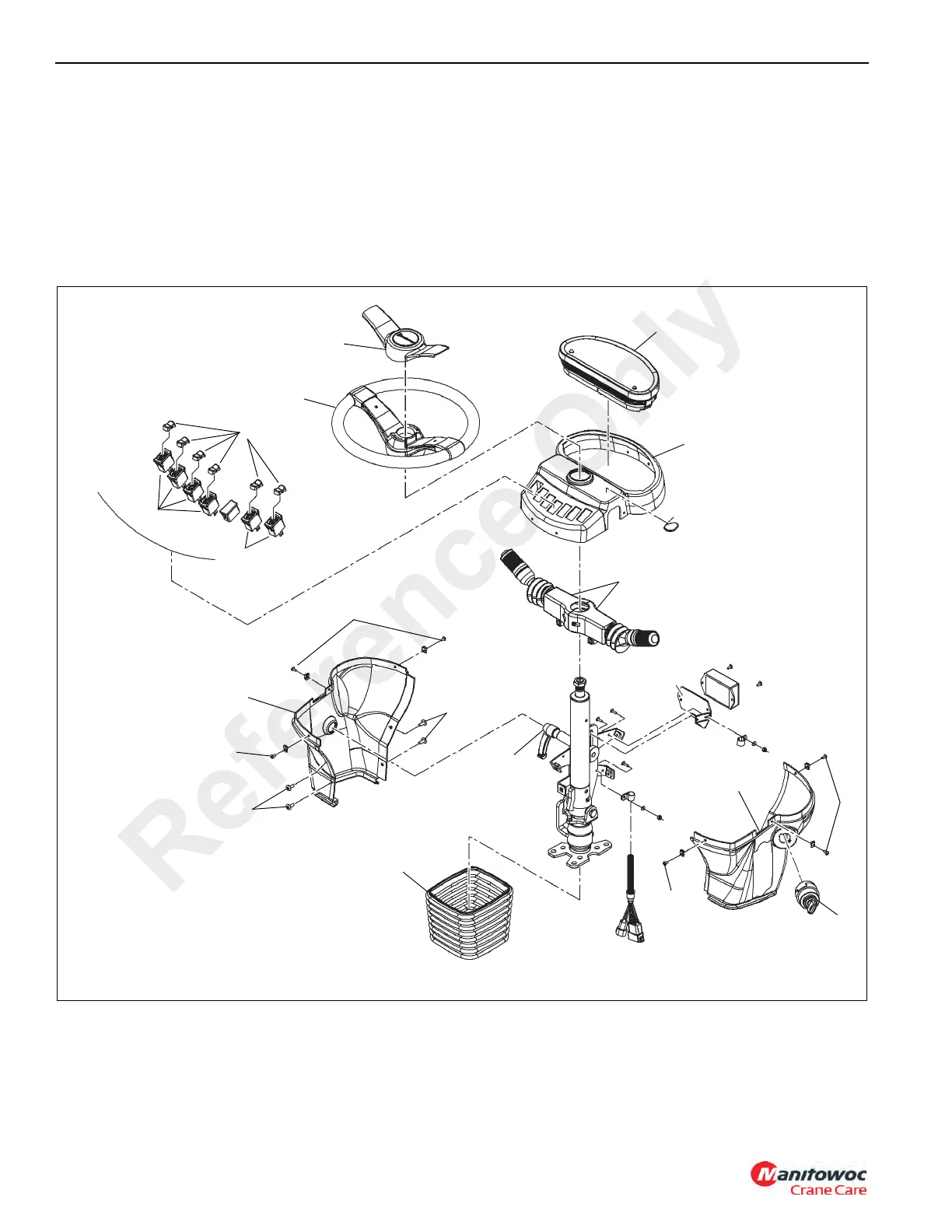
12. Install the steering wheel (2); torque the securing nut to
30 lb-ft ±4 (40 Nm ±5).
13. Install the steering wheel cap (1).
14. Install the lever (12) and spacer that locks/unlocks the
steering column tilt/telescope function.
15. Pull the rubber boot (11) up and over the bottom of the
left and right side covers (8, 9).
16. Turn the battery disconnect switch to the ON position.
Check
1. Operate the turn signal lever or transmission shift lever
per the Operator’s Manual. Verify each of its functions
work.
2. As needed, troubleshoot further any system or circuit
malfunction not corrected by repair or replacement of
the switch or associated wiring.
FIGURE 3-9
7794-1
9
10
13
14
11
12
1
2
3
4
5
6
7
8
13
14
14
14
4
Reference Only
 Loading...


