BOOM RT765E-2 SERVICE MANUAL
4-6
Published 9-04-2014, Control # 422-08
1. Extend and set the outriggers to level the crane and
ensure the boom is fully retracted and in a horizontal
position over the front of the crane.
2. If equipped, remove the swingaway boom extension
according to the removal procedures in this section.
3. Remove the hook block or headache ball and wind all
the wire rope onto the hoist drum.
4. Elevate the boom slightly to allow for withdrawal of the
lift cylinder rod end from the lift cylinder attach fitting on
the bottom of the boom.
5. Attach a lifting device to the boom to provide for equal
weight distribution.
6. Disconnect any electrical wiring from the boom.
7. Tag and disconnect the hydraulic lines to the telescope
cylinder. Cap the lines and openings.
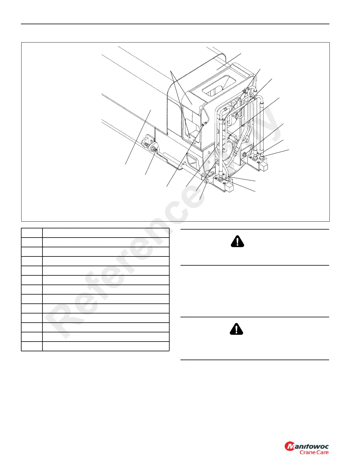
FIGURE 4-2
NOTE: Boom assembly must be
rotated 180° before
performing assembly or
disassembly procedures.
NOTE: Inner Mid extend cable
anchor plate not shown
for clarity.
6
4
1
2
3
5
7
8
9
11
12
10
8
9
8
9
Item Description
1 Wear Pad
2Port P
3 Inner Mid
4 Base Section
5Port R
6Port C
7 Tapped Pusher Bar
8Port B
9Port A
10 Pusher Bar
11 Grease Line
12 Trigger Weld
CAUTION
Wear gloves when handling wire rope. Moderate to minor
injury may result if using bare hands.
WARNING
Ensure the lifting device is capable of supporting the
boom assembly. Death or serious injury may result if the
lifting device cannot support the load.
Reference Only
 Loading...


