6-11
Published 9-04-2014, Control # 422-08
RT765E-2 SERVICE MANUAL SWING SYSTEM
3. Multiplier bar handles must be propped or supported
within the outer 1/4 of the handle length, or serious
under or over tightening will occur.
4. The inner race of the bearing is secured to the turntable
by 44, one-inch Grade 8 bolts. The outer race of the
bearing is secured to the carrier frame by 40, one-inch,
Grade 8 bolts.
Tools Required
The figure (Figure 6-3) illustrates and lists the complete set
of special tools required to torque the turntable bolts.
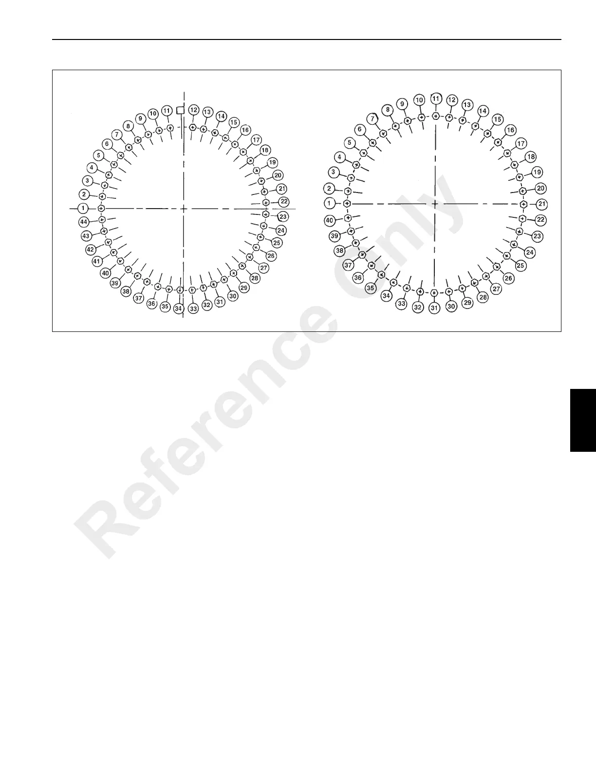
Inner Race Torquing
1. Extend and set the outriggers. Fully elevate the boom.
2. Torque eight bolts to 80% of their specified torque value
using the following sequence pattern; 12, 34, 23, 2, 17,
39, 28 and 7; refer to Fasteners and Torque Values,
page 1-16 for proper torque value. Tools used are the
socket, multiplier, backlash adapter, necessary
extensions, and torque wrench.
3. Return to bolt 1 and torque all bolts sequentially in a
clockwise direction to their final torque value specified.
The same tools are used as in step 1.
Outer Race Torquing
1. Extend and set the outriggers. Fully elevate the boom.
2. Torque eight bolts to 80% of their specified torque value
using the following sequence pattern; 11, 31, 11, 21, 1,
16, 36, 26 and 6; refer to Fasteners and Torque Values,
page 1-16 for proper torque value. Tools used are the
socket, multiplier, backlash adapter, necessary
extensions, and torque wrench.
3. Return to bolt 1 and torque all bolts sequentially in a
clockwise direction to their final torque value specified.
The same tools are used as in step 1.
Removal
1. Fully extend and set the outriggers enough to take up
the slack in the pads.
NOTE: Do not raise the machine on the outriggers.
2. Ensure the boom is in the travel position and the
turntable lock pin is engaged.
3. Elevate the boom slightly and shut down the engine.
4. Tag and disconnect the battery cables from the
batteries.
5. Remove the boom and lift cylinder following the
procedures outlined in Section 4 - Boom.
NOTE: The fixed counterweight weighs approximately
14,400 lb (6540 kg). The removable counterweight
weighs approximately 14,860 lb (6740 kg)
6. Remove the counterweight. Refer to Hoist and
Counterweight, page 5-1.
7. Tag and disconnect all water and oil lines from the
bottom of the swivel. Cap or plug all lines and openings.
8. Locate the connectors and ground wire that joins the
swivel wiring harness to the receptacles and ground
stud on the carrier.
FIGURE 6-2
Outer Race
Inner Race
Reference Only
 Loading...


