GROVE Published 1-20-2017, Control# 483-02 6-3
CD5515-2/YB5515-2 SERVICE MANUAL ENGINE AND ENGINE SYSTEMS
protection will never be required, use a non-chromate
corrosion inhibitor and clean soft water. Change the
water/corrosion inhibitor every 12 months, or 500 hours,
or to manufacturer’s recommendation.
Do not use hard water in the cooling system. Hard
water, or water with high levels of calcium and
magnesium ions, encourages silica gel formations,
especially after a number of heating and cooling cycles.
These gel formations can result in loss of cooling or
heating in radiators and cab heater cores by coating and
plugging the tubes. The formations usually deposit in the
cooler sections of the cooling system, such as the
radiator bottom tank.
Use soft water, distilled water or deionized water to
reduce the potential and severity of silicate dropouts.
NOTE: If you use water without a corrosion inhibitor, rust
will form and plug the small holes in the head
gasket. These holes are orifices and their size is
critical. Do not enlarge the size of the orifices. To do
so will disturb the coolant flow and will not solve
any overheating problem. If you use water without
a corrosion inhibitor for even a short period, the cup
plugs will rust through, allowing coolant leakage.
An incorrect or malfunctioning radiator cap can
result in the loss of coolant and engine running hot.
Any sudden loss of coolant from a heavily loaded
engine can result in severe damage to the pistons
and cylinder bore.
NOTE: Some corrosion inhibitor mixtures contain soluble
oil which can have an adverse effect on some
types of water hoses.
Radiator Cap and Overflow Bottle
The cooling system is designed to use a radiator cap to
prevent the boiling of coolant. The radiator cap is set to open
at 0.97 bar (14 psi). When it does open it allows coolant to be
expelled into the overflow bottle and as soon as the engine
cools the overflow fluid is sucked back into the radiator. An
incorrect radiator cap can result in a great loss of coolant and
the engine running hot.
Keep the overflow bottle at least half full of coolant at all
times.
Thermostat
A malfunctioning thermostat can result in the engine running
hot or cold. If it becomes necessary to replace the thermostat
see the engine manual furnished with the crane.
ENGINE ELECTRICAL SYSTEM
The engine electrical system, the charging and starting
circuits, as well as the sending units, are described in this
section.
ENGINE FUEL SYSTEM
Diesel Engine Fuel System Description
The diesel engine fuel system is a closed-loop fuel system
which includes a fuel tank, an engine fuel filter, an engine
fuel pump and the fuel lines.
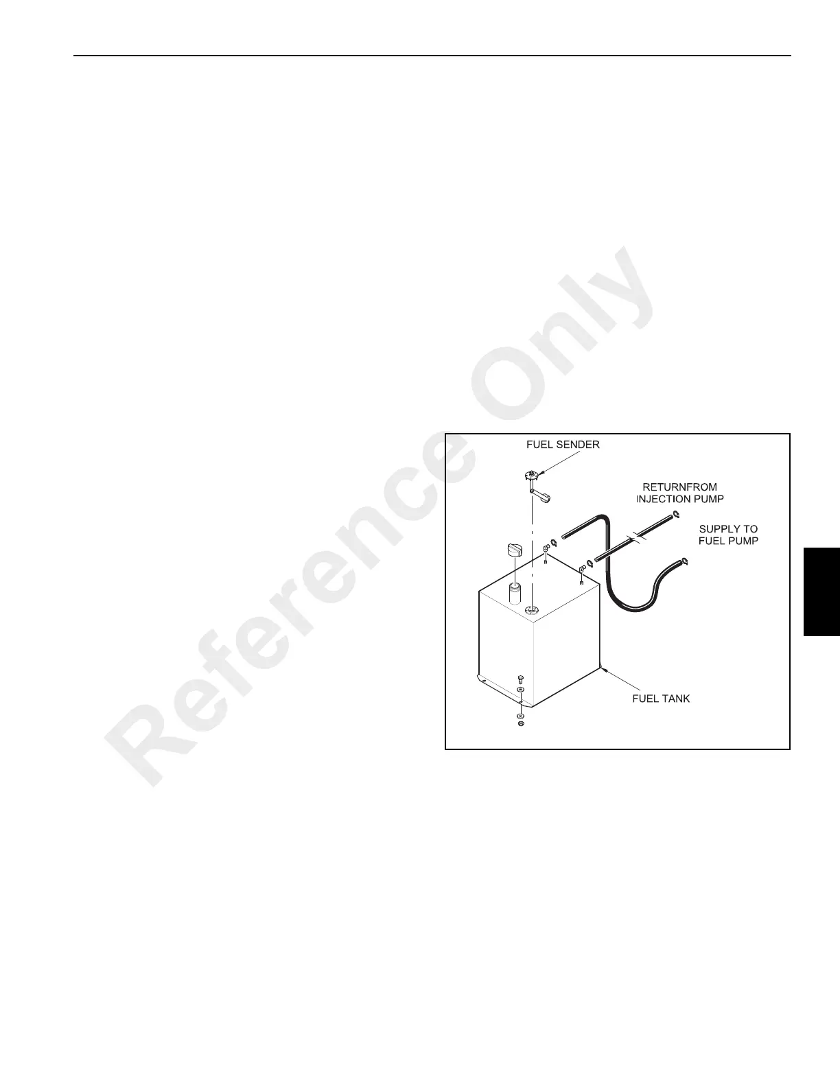
A fuel supply line carries fuel from the bottom of the fuel tank
to the engine fuel pump Figure 6-2. A line carries the fuel
from the engine fuel pump to the engine fuel filter. Fuel that
has been filtered flows to the fuel injector pump.
Fuel is distributed to the fuel injectors from the fuel injector
pump. Excess fuel from the fuel injector pump is returned to
tank.
Fuel Tank
The fuel tank is located on the right side of the crane. It is a
welded box construction with a suction tube installed in the
fuel support port. The tube inhibits sediment and water from
being picked up off the bottom and sent to the engine.
Fuel Level Sender and Gauge
The fuel level sender and gauge are described in the Section
11, Electrical System.
Fuel Pump
The fuel pump is installed internally in the engine and is used
to pump fuel from the fuel tank and send it under pressure to
the fuel filters and injection pump.
The fuel pump includes a priming button. This button is used
to bleed the fuel system if one of the following should occur:
• The fuel filter is not filled prior to installation.
• The injection pump is replaced.
A1768
FIGURE 6-2
Diesel Fuel System
Reference Only
 Loading...


