GROVE Published 1-20-2017, Control# 483-02 9-19
CD5515-2/YB5515-2 SERVICE MANUAL
5. Remove end plug 8 and spring 10 from housing 12.
Remove O-ring 9 from plug 8.
6. Carefully remove spool 11 from end plug 8 end of
housing 12.
NOTE: Be careful not to damage the spool or housing bore
as they are a matched set and not sold separately.
Assembly
A seal kit is available for repair of the valve. It consists of the
items indicated with a in Figure 9-29.
NOTE: Lubricate all rubber components in repair kit with
clean hydraulic oil of the same type used in the
hydraulic system.
1. Clean all parts before assembling. Use a suitable
solvent.
2. Lubricate spool 11 Figure 9-29 with clean hydraulic oil
and carefully slide into plug end of housing 12.
NOTE: The spool must slide freely into the bore. If either
part is damaged, a new valve assembly may be
required.
3. Install new O-ring 9 on end plug 8.
4. Install spring 10 and end plug 8 into housing 12. Tighten
to a torque of 54.2 - 67.8 Nm (40 - 50 lb-ft).
5. Carefully install new cup 14 and new seal 15 into bore of
housing 12. Make sure they are installed in the proper
order and direction. Take care when installing not to
scratch or mar the housing bore.
6. Assemble springs 3, 4 and 5, shims 6 and retainer
assembly 7 into piston 2.
7. Carefully install piston 2 assembly into bore of housing
12.
8. Install new boot 1 on housing 12 and piston 2.
9. Install the valve assembly onto the pedal assembly with
new capscrews (13). Tighten to a torque of 24.4 -
29.8 Nm (18 - 22 lb-ft).
10. After final assembly, the valve must develop a pressure
of 37.92 ± 3.45 bar (550 ± 50 psi).
Installation
1. Place the brake modulating valve and pedal assembly in
location in the operator’s cab. Secure to the cab floor
with three capscrews and self-locking nuts.
2. Connect the three hydraulic hoses to the valve.
3. Open the accumulator needle valve and then start the
engine. Allow pressure to build in the brake system.
4. Bleed air from the brake system. See page 9-6.
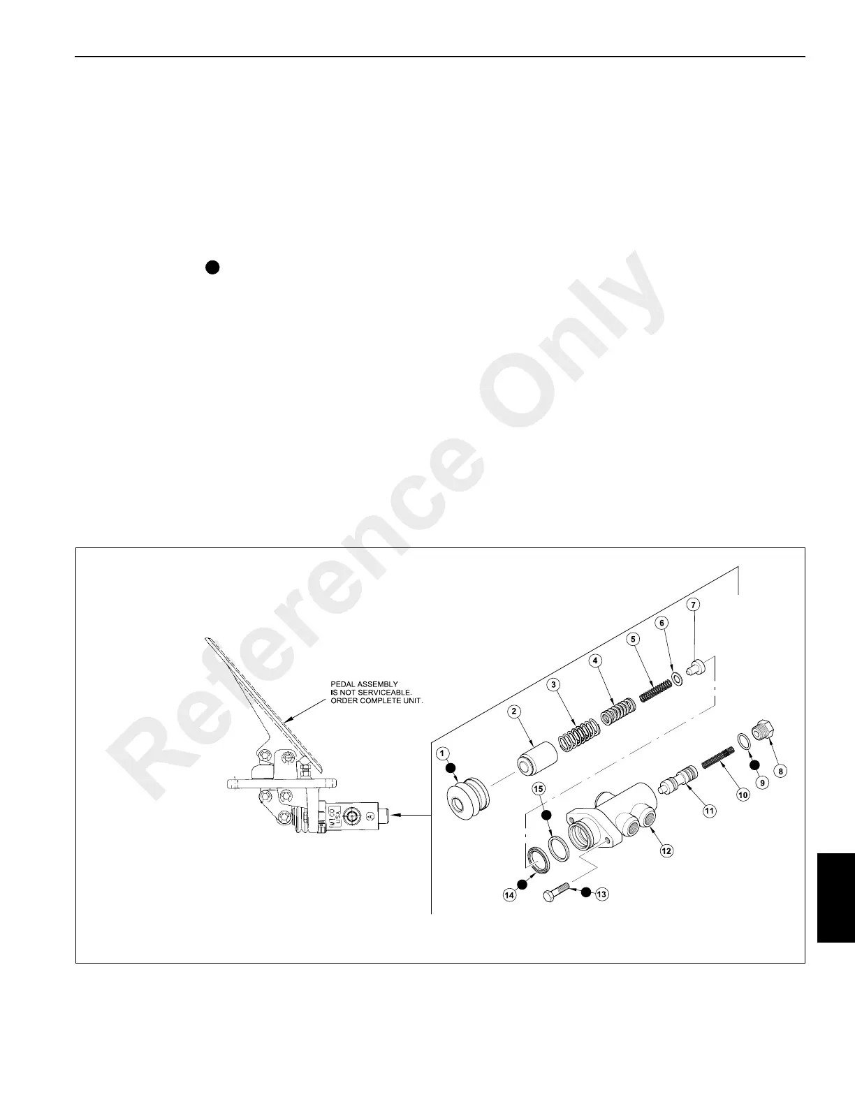
FIGURE 9-29
a0780
1. Boot
2. Piston Assembly
3. Spring
4. Spring
5. Spring
6. Shim
7. Retainer Assembly
8. End Plug
9. O-ring
10. Spring
11. Spool
12. Housing
13. Screw
14. Cup
15. Seal
Brake Modulating Valve
Reference Only
 Loading...


