GROVE Published 1-20-2017, Control# 483-02 3-7
CD5515-2/YB5515-2 SERVICE MANUAL ELECTRIC SYSTEM
INSTRUMENT AND LIGHT CIRCUITS
General
Power is available to the light switch from a 20 amp fuse on
the fuse block. The light switch has three positions. The
upper position illuminates the work lights, head lights, tail
lights, gauge lights and the instrument panel light. The center
position turns all lights off. The lower position illuminates the
head and tail lights, as well as, the instrument panel lights.
Light Bulbs
Table 3-2
Light Bulbs
Gauges and Indicators
The gauges are 12 volt components. Power is available to
the gauges through a 5 amp fuse when the ignition switch is
in the ON position.
Fuel Gauge
The fuel gauge connects to a sending unit in the fuel tank.
This sending unit puts a variable resistance in the circuit and
causes a corresponding indication on the fuel gauge,
representing fuel level.
Engine Oil Pressure Indicator
This indicator connects to the engine ECM. The ECM
connects to a sending unit in the engine lubrication system.
When the oil pressure is below a predetermined value the
sending unit signals the ECM indicating engine oil pressure
is too low.
Engine Temperature Gauge
This gauge connects to the engine ECM. The ECM connects
to a sending unit in the engine cooling system. The variable
resistance caused by the sending unit gives a corresponding
indication of the temperature of the engine coolant.
Voltmeter Display
The voltmeter is connected in parallel with the charging
circuit. The voltmeter gives an indication of electrical
charging system problems that can not be seen with an
ammeter.
Normally, when the engine is stopped (ignition switch in the
ON position) or when the engine is running at low idle, the
voltmeter will indicate 11-14 volts. When the engine is
running above low idle, the voltmeter will normally indicate
14-16 volts. More than 16 volts indicates an overcharging
condition Table 3-3.
Hour Meter
Power is available through the oil pressure switch on the
engine by way of the engine ECM. The hour meter operates
only when the engine is running.
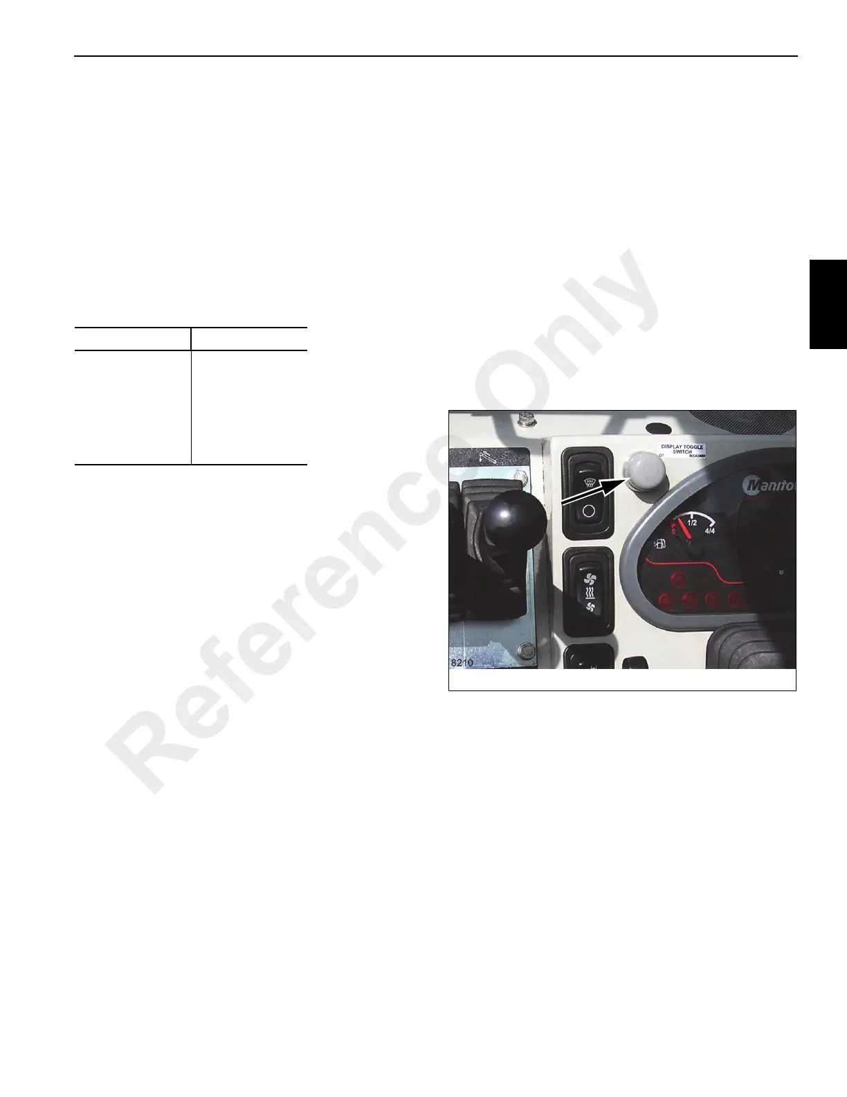
ECM Display Toggle Switch
The Display Toggle Switch is used to display engine ECM
error codes. With the engine running, press the button and
no engine codes are present the display cluster will read “No
Errors Detected”. If a single error code is present, it will be
displayed when the button is pressed. If multiple error codes
are present, the display will list in the parentheses the
number of error codes and will scroll through them in order of
occurrence each time the button is depressed.
Location Trade No.
Head Lights 4411 Sealed
Tail Lights 1157
Turn Signal 1156
Work Lights 4411 Sealed
Mast Lights 4411 Sealed
Reference Only
 Loading...


