HYDRAULIC SYSTEM CD5515-2/YB5515-2 SERVICE MANUAL
4-8 Published 1-20-2017, Control# 483-02
HYDRAULIC SYSTEM
System Description
The hydraulic system is a closed-center hydraulic system
with pressure compensated load sensing characteristics
driven by a variable displacement axial piston pump.
Hydraulic Pump
Description
The hydraulic pump is a variable displacement axial piston
pressure compensated pump. The pump generates a fluid
flow and imparts to that fluid the necessary pressure forces
to obtain the hydraulic system pressure.
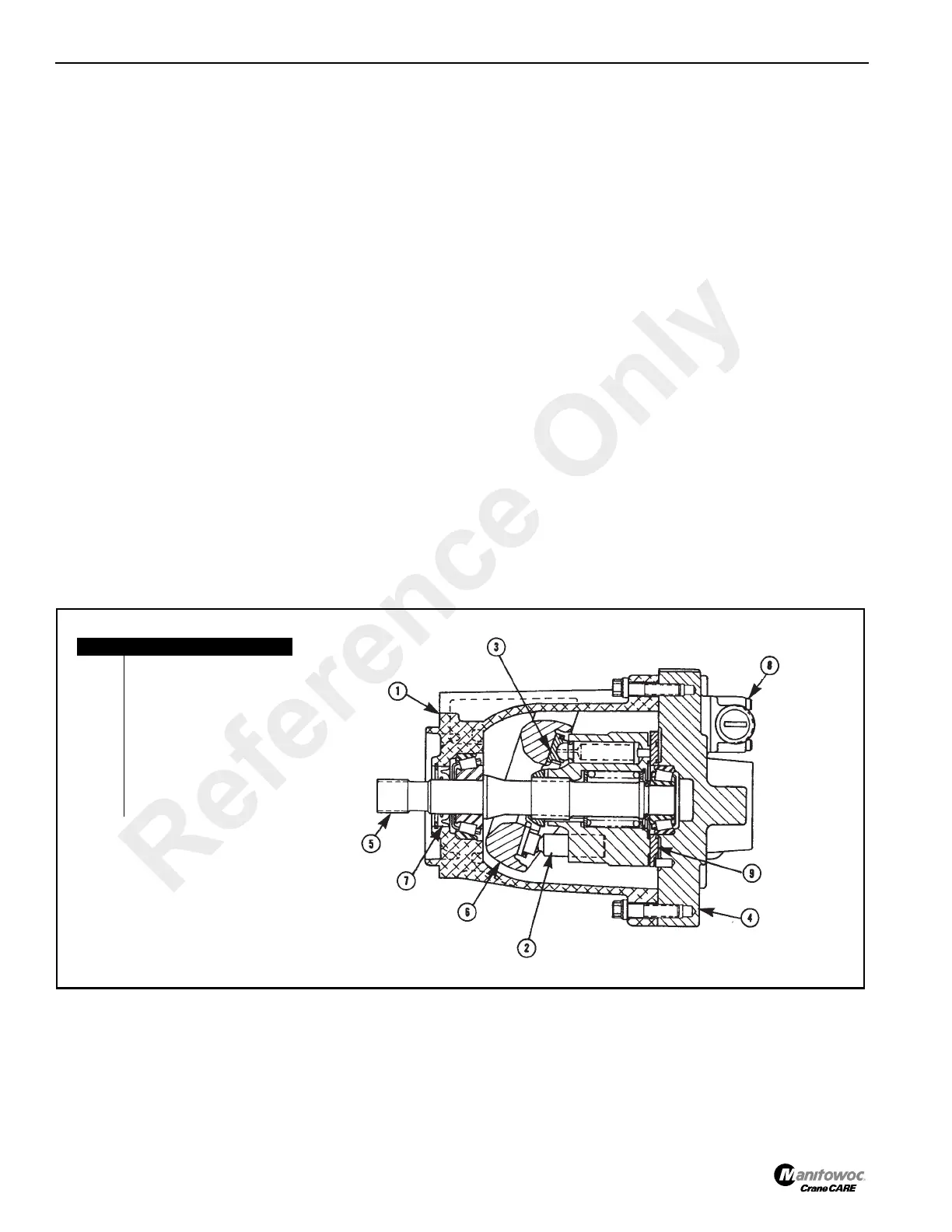
The pump basically consists of the housing (1, Figure 4-1),
piston (2), shoes (3), port plate (4), drive shaft (5), swash
plate (6), shaft seal (7), compensator (8) and valve plate (9).
Rotation of the drive shaft (5) and control piston (not shown)
causes a linear piston movement as the piston shoe (3)
slides along the tilted swash plate (6). As the piston retracts
in the cylinder bore, hydraulic oil from the hydraulic oil tank
fills the developing vacuum cavity by way of the suction
kidney in the valve plate (9). At maximum retraction of the
piston, shaft rotation causes the piston to go beyond the
suction kidney and begin communication with the pressure
kidney. Continuing rotation then extends the piston into the
cylinder bore, forcing oil into the pressure port and out to the
hydraulic system.
Test - Pump Output
The hydraulic pump output can not be checked using a
flowmeter. The efficiency of the pump must be checked by
using function cycling speeds.
Pressure Regulation
System pressure is working on the pressure compensator
against a setting spring. When system pressure overcomes
the spring force, the spool shifts allowing system pressure
into the control piston. This causes the pump to stroke to a
regulating point sufficient to maintain the increased
compensator setting (system pressure) and the lubrication
fluid flow required.
When the system pressure setting is reached, only the
amount of fluid necessary to satisfy the load conditions is
delivered. If the load condition is such that no flow is
required, only cooling and lubricating fluid is delivered.
Power usage and heating of the fluid are kept to a minimum.
When the system pressure falls below the compensator
spring setting, spring force returns the spool back to the
normal position, which drains the control piston (2,
Figure 4-1) to the pump case drain. This causes the pump to
de-stroke, reducing the fluid flow to the level required.
Description of Operation
Hydraulic System
The hydraulic system is a closed-center hydraulic system.
Which means that hydraulic oil is blocked from returning to
tank when the valves spools are in the neutral position. The
control valve sections used in the hydraulic system of the
main control valve are pressure compensated valve sections
incorporating a flow divider principle in their operation. This
provides the ability to control multifunction operation when
flow demand exceeds pump capacity though slowed down
proportionally. This means that all circuits will continue to
FIGURE 4-1
Item Description
1 Housing
2Piston
3 Shoe
4 Port Plate
5 Drive Shaft
6Swash Plate
7 Shaft Seal
8 Compensator Control
9Valve Plate
a0727
Reference Only
 Loading...


