GROVE Published 1-20-2017, Control# 483-02 6-5
CD5515-2/YB5515-2 SERVICE MANUAL ENGINE AND ENGINE SYSTEMS
ENGINE AIR INTAKE SYSTEM
Air for combustion is pulled through an air filter by the
engine. Dust and foreign materials are removed from the air
by the air filter.
Replace or clean the air filter at the intervals given in
Preventative Maintenance, Section 5. Make sure all clamps
on the intake tube and filter are tight. If dust or foreign
materials enter the engine, permanent damage can be
caused to the engine.
NOTE: NEVER run the engine without an air cleaner
installed.
ENGINE EXHAUST SYSTEM
Exhaust system components get very hot and can cause
severe burns.
The exhaust system is installed under the frame to minimize
the transfer of noise and vibration into the operator’s
compartment.
Annoying rattles and noise vibrations in the exhaust system
are usually caused by misalignment of parts. When aligning
the system, leave all bolts and nuts loose until all parts are
properly aligned, then tighten working from top to bottom.
When installing exhaust parts, make sure there is sufficient
clearances between the hot exhaust parts and parts that
would be adversely affected by heat.
When installing an exhaust system, allow for expansion
when the system is hot.
Periodic maintenance of the exhaust system is not required,
However, it is advisable to check the condition of the system
when performing other maintenance on the crane.
Check the complete exhaust system for broken, damaged,
missing or mispositioned parts, open seams, holes, loose
connections and other deterioration which could cause
exhaust fumes to seep into the operator’s compartment. Any
damaged areas must be corrected.
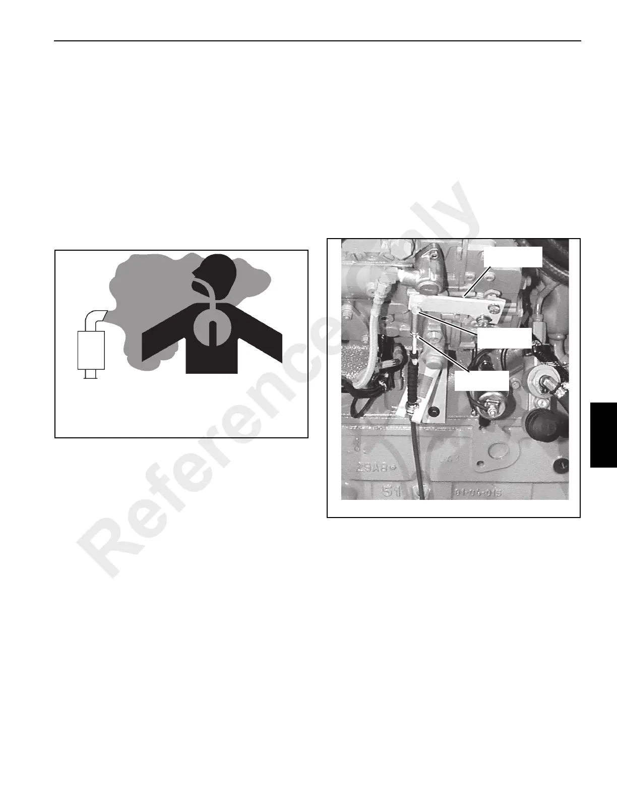
CHECKS AND ADJUSTMENTS
Throttle Linkage Adjustment
Adjustment of the throttle linkage is made by adjusting the
travel distance of the throttle cable.
1. Remove the ball joint Figure 6-5 from the throttle control
lever.
2. Loosen the jam nut and turn the ball joint clockwise to
increase throttle speed and counterclockwise to
decrease throttle speed.
3. Connect the balljoint to the throttle lever and then tighten
the jam nut.
NOTE: Maximum speed for the engine is 2500 rpm. Main
hydraulic pump damage could occur from a higher
RPM setting. Never set engine speed higher than
2500 rpm.
w0002
EXHAUST FUMES CAN BE FATAL. When operating in
enclosed areas with a gasoline or diesel engine, provide
adequate ventilation.
FIGURE 6-4
p0096
FIGURE 6-5
Throttle Lever
Ball Joint
Jam Nut
Reference Only
 Loading...


