GROVE Published 1-20-2017, Control# 483-02 4-19
CD5515-2/YB5515-2 SERVICE MANUAL HYDRAULIC SYSTEM
ANTI-DOUBLE BLOCKING SYSTEM
General
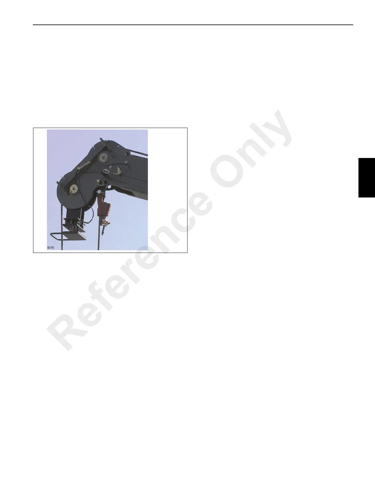
The anti-double block circuit protects the hoist, telescope
and lift circuits from damage in the event that the hoist block
comes in contact with the boom head causing a double
blocking situation. The anti-double block system includes an
anti-double block mechanism Figure 4-10 at the end of the
boom head, a valve block with three normally closed
solenoids, and a check valve in the main control valve
sections for lift, telescope and hoist functions.
System Function
The main control valve sections for the hoist, telescope and
lift functions each have a check valve installed internally.
This check valve is connected to the return passage in the
valve section and to port A of the valve section. Its primary
function is to release hydraulic oil back to tank whenever the
anti-double block solenoid valves are open (de-energized).
During normal operation the solenoid valves are in the
closed (energized) position (Figure 4-7). In the closed
position oil under pressure is stopped by the solenoid valve
from returning to tank. The blocked fluid under pressure
passes through a restriction in the valve section to the check
valve. The check valve is held closed by a combination of the
check valve spring and oil pressure from the closed solenoid
valve. In combination, the oil pressure and spring pressure is
greater than the return oil pressure and the check valve is
kept closed. Return oil is then directed through the valve
spool to the outlet port of the control valve.
When the hoist block comes in contact with the anti-double
blocking bracket at the end of the boom head, the bracket
raises and actuates a switch. This switch, when actuated,
closes an electrical signal to the three solenoid valves
opening them Figure 4-8. With the solenoid valves open, oil
supply to the check valve is reduced. The check valve spring
alone is not enough to hold the check valve closed,
therefore, the check valve opens. With the check valve open,
hydraulic oil which would normally flow to the lift cylinder,
telescopic cylinder or hoist motor through port A of the valve
section is returned through the check valve to the outlet of
the control valve, or through the open solenoid valve, back to
tank.
Lowering the hoist block will deactivate the switch to close
the solenoid valves and return flow through port A to the
function.
OUTRIGGER AND AXLE LOCK OUT
CIRCUITS
Independently Controlled Outrigger
Hydraulic System
The independently controlled outrigger hydraulic system
includes a priority flow control valve, an accumulator
charging valve, a dump valve, the first eight solenoid valves
of the outrigger valve, four horizontal outrigger cylinders and
four vertical outrigger cylinders with holding valves.
Oil Flow
Oil from the fourth pump section flows at a rate of 60.5 L/min
(16 gpm) to the priority flow control valve. The priority flow
control valve reduces the flow rate to 45.4 L/min (12 gpm) to
the accumulator charging valve. It then passes through the
accumulator charging valve to the dump valve. If the dump
valve is energized (actuation of an outrigger switch) the oil
flows to the outrigger valve. Depending upon which outrigger
function is activated (solenoid valve energized), the oil flows
through outrigger valve section to the outrigger. The cylinder
extends or retracts and pushes oil ahead of the piston
through one of the ports of the cylinder. The oil returns
through outrigger control valve back to tank through the
return filter.
Outrigger Valves
Description
The front outrigger valve consists of a manifold, relief valve,
and five solenoid valves. The fifth solenoid valve is used to
control the optional under deck winch.
The rear outrigger valve consists of a manifold, relief valve,
and five solenoid valves, the fifth valve is used to control the
axle oscillation cylinders.
Each solenoid valve has a closed-center passage, blocking
oil at the valve and preventing oil from returning to tank
unless the spool is shifted. Oil from the manifold inlet flows
directly to each valve section where it stops. When a section
solenoid is activated, the spool moves allowing oil to flow
through the solenoid valve section and manifold to the
outrigger cylinder. Return oil from the cylinder flows through
the valve section back to tank.
Reference Only
 Loading...


