HYDRAULIC SYSTEM CD5515-2/YB5515-2 SERVICE MANUAL
4-20 Published 1-20-2017, Control# 483-02
A relief valve set at 144.79 ± 3.45 bar (2100 ± 50 psi) is
installed in the inlet of the manifold, protects the outrigger
circuits from high pressure buildup.
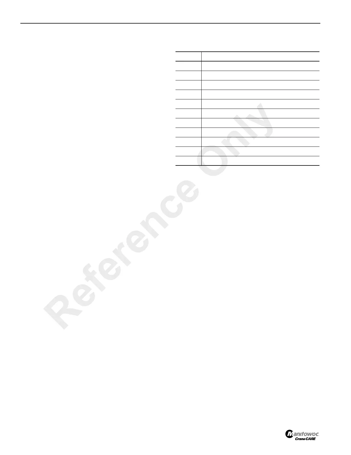
Outrigger Valve Ports
For easy identification, the ports of the outrigger valve are
stamped on the valve manifold.
Table 4-7: Port Identification Figure 4-11
Port Function
1 Under Deck Winch
2 Left Front Jack Cylinder
3 Left Front Beam Cylinder
4 Right Front Beam Cylinder
5 Right Front Jack Cylinder
A1 Front Outrigger Beam and Jack Return
A2 Not Used
A3 Rear Outrigger Manifold Return
A4 Under Deck Winch Return
P From Pump
T To Tank
Reference Only
 Loading...


