TRANSMISSION AND TORQUE CONVERTER CD5515-2/YB5515-2 SERVICE MANUAL
7-16 Published 1-20-2017, Control# 483-02
Checking for (+ V) Supply to Solenoids
1. Chock all four tires, or lower all outriggers.
2. Disable the machine neutral start protection to prevent
the engine from starting. This can be accomplished by
removing the neutral start relay located beneath the
dash Figure 7-12.
3. Turn the ignition switch to the ON position. Do not set the
parking brake as this dumps the transmission to a
neutral state.
4. Select the desired gear on the shift control lever.
5. Identify the two solenoids which give the required gear
Figure 7-11.
6. Remove the electrical connector on the solenoids
relating to gear selection.
7. Test across the connector terminals with a test lamp or
voltmeter.
When using a voltmeter for the above check, the
following results can be seen.
- Energized solenoid (ON) = full battery charge.
- De-energized solenoid (OFF) = reduced voltage
(Typically 5 - 9 V).
This reduced voltage should not be interpreted as a problem.
When an electrical load is placed across the terminals this
voltage drops to zero.
Checking the Main Frame Harness
NOTE: The following checks should be carried out with the
parking brake DISENGAGED.
1. Chock the four tires, or lower all outriggers.
2. Disable the crane neutral start protection to prevent the
engine from starting. This can be accomplished by
removing the neutral start relay located beneath the
dash Figure 7-12.
3. Disconnect the main frame wire harness from the ECU.
The main frame wire harness connector is the larger of
the two ECU connectors.
4. Check the condition of the connector and socket for
signs of water entry. Check the condition of the rubber
seal in the instrument panel wire harness connector.
5. Turn the ignition switch to the ON position. Do not set the
parking brake as this dumps the transmission to a
neutral state.
6. Test the voltages on the pins in the harness connector
(DO NOT check the ECU pins) using a test lamp or
voltmeter. Refer to Table 7-2 for pin identification.
7. If the lamp illuminates, or the voltmeter shows full
battery charge, where indicated in the table, then the
integrity of the harness and power supply to the ECU is
verified.
Checking Parking Brake Switch
The correct operation of the parking brake can be checked
using either of the following tests:
1. Check continuity between pin 8 and ground (pin 11 or
12) when parking brake is applied.
2. Connect a test lamp between pin 23 or 24 and pin 8.
The lamp will illuminate when the parking brake is
applied.
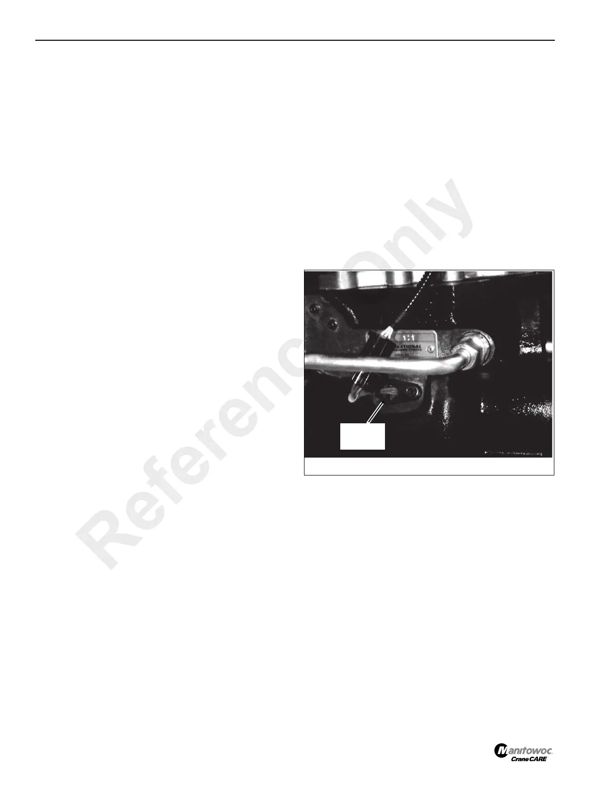
Checking Sensor Operation
The speed sensor Figure 7-13 detects the speed of rotation
of the output shaft for the transfer gear and sends this
information to the ECU.
The ECU requires a speed signal to determine the operating
speed of the crane. Some gear selections will not be
permitted if the speed signal is too high (i.e. downshifts).
NOTE: The ECU is designed to inhibit 4th gear selection if
the speed sensor fails to send a signal.
A test lamp should be used to check operation of the speed
sensor, as follows:
1. Park the crane on a firm, level ground. Engage the
parking brake and set the forward/reverse lever to the
neutral position.
2. Turn off the engine and remove the ignition key.
3. Disconnect the speed sensor from the wire harness.
4. Remove the speed sensor from the transmission. Place
a suitable container underneath to catch the oil.
5. Check that the sensor is working by connecting a volt/
ohm meter to the pins in the speed sensor connector
and checking the voltage reading. Connect the positive
FIGURE 7-13
p0716
Speed
Sensor
Reference Only
 Loading...


