GROVE Published 1-20-2017, Control# 483-02 8-9
CD5515-2/YB5515-2 SERVICE MANUAL AXLES/DRIVE SHAFTS/WHEELS AND TIRES
16. Remove drive shaft 21 from the axle casing.
17. Pry out drive shaft inner oil seal 2.
18. Using a bearing puller, remove bearing 1.
19. Pry out drive shaft inner seal 31B.
20. Remove retaining ring 32.
21. Using a bearing puller, remove bearing 33.
22. If there has been a component failure, remove all traces
of debris and clean the magnetic drain plug.
Assembly
NOTE: The top and bottom trunnions are very similar
(bottom trunnion not shown), the only difference
being that shims 28 are installed to the top trunnion
only.
1. Tap the drive shaft inner bearing 33 Figure 8-8 into
position in the hub swivel drive shaft bore. Secure with
retaining ring 32.
2. Install a new oil seal 31 Pack grease between lips of the
seal.
3. Install drive shaft 21, taking care to locate inner end into
the splines of the differential gears.
4. Tap drive shaft outer bearing 1 into position in the hub
swivel.
5. Install new oil seal 2. Pack grease between the lips of
the seal.
6. Press new top and bottom oil seals 29 into position
followed by bearings 30. Grease bearings and oil seal
before installing in axle.
7. Locate hub swivel 3 and install bottom trunnion 27.
Apply Loctite® 243 to the threads of the bottom trunnion
bolts 26 and then tighten to a torque of 56 Nm (42 lb-ft).
Install top trunnion 27 with normal 0.25 mm (0.10 in)
shim 28 and leave top trunnion bolts 26 finger tight).
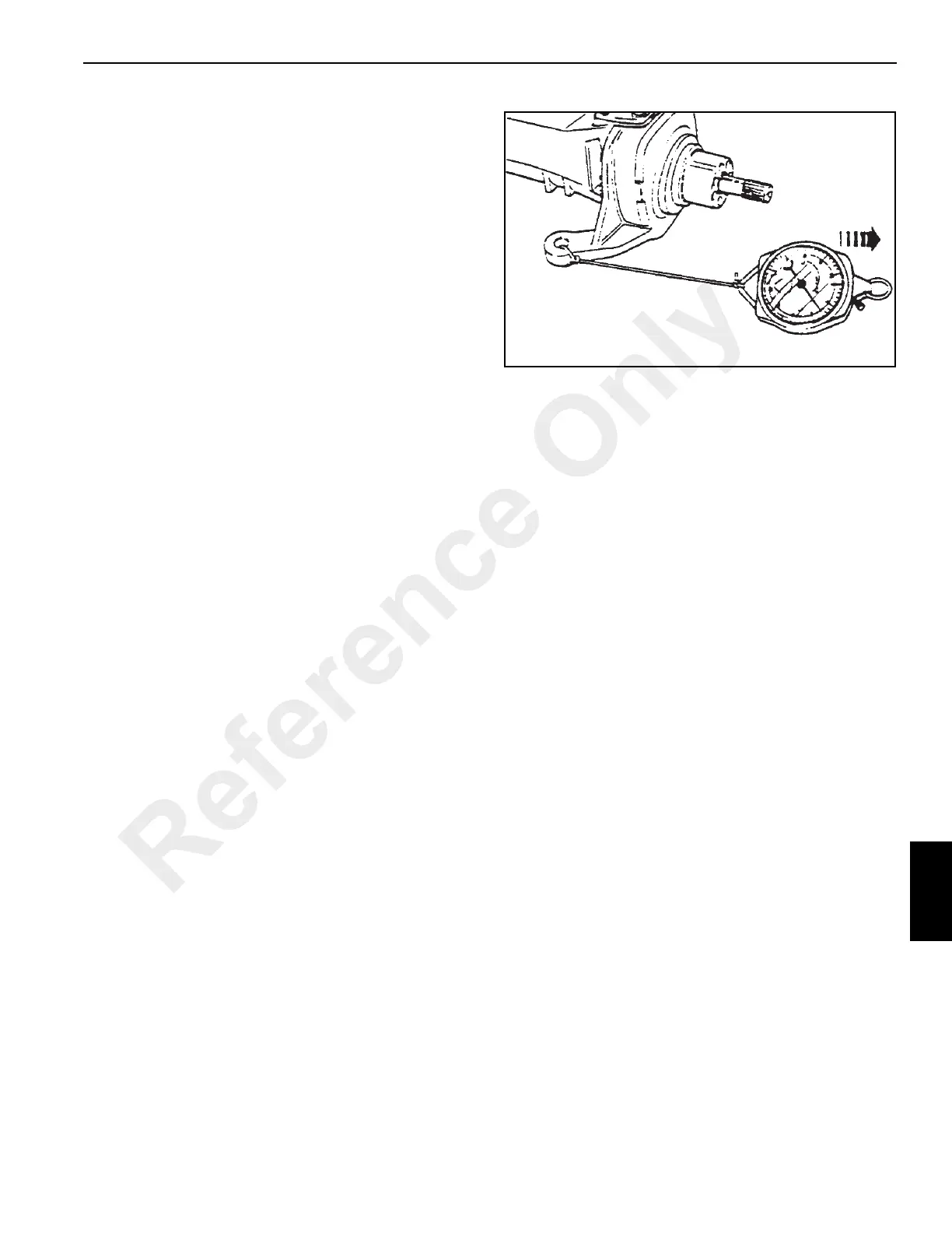
8. Attach a spring balance (Figure 8-9) to track rod swivel
and turn the swivel. Tighten the top trunnion bolts 26 to
eliminate end float but without bearing pre-load, that is,
no increase in spring balance reading.
9. Measure the gap at the top trunnion and subtract 1 mm
(0.040 inches) to give shim thickness (bearing pre-load).
For example:
NOTE: If the gap measures 1 mm (0.040 inches), then no
shim is required.
If after installing the shims, the bearing pre-load is
not attainable, install new bearings.
10. Reinstall the top trunnion. Apply Loctite® 243 to the top
trunnion bolt threads, install and tighten to a torque of 56
Nm (42 lb-ft).
Check the spring balance reading which should be 4.5
kg (10 lb) more than the reading recorded in step 8.
11. Connect the track rod and steering cylinder to the axle
steering knuckle. Tighten the track rod nut to a torque of
135 Nm (100 lb-ft), then continue to tighten to next
castellation and insert the pin.
12. Lightly oil the inner wheel bearing 6 and its cup 17. Then
install them into bearing carrier 8.
13. Install a new combination seal 9 into the bearing
carrier 8.
Do not lubricate before installing. Drive the seal squarely
into the bearing carrier
8 until the
locating lip is flush, as
shown in X Figure
8-10.
Gap = 1.55 mm (0.061 inches)
less = 1.00 mm (0.040 inches)
Shim = 0.55 mm (0.021 inches)
Reference Only
 Loading...


