GROVE Published 1-20-2017, Control# 483-02 10-25
CD5515-2/YB5515-2 SERVICE MANUAL STEERING SYSTEM
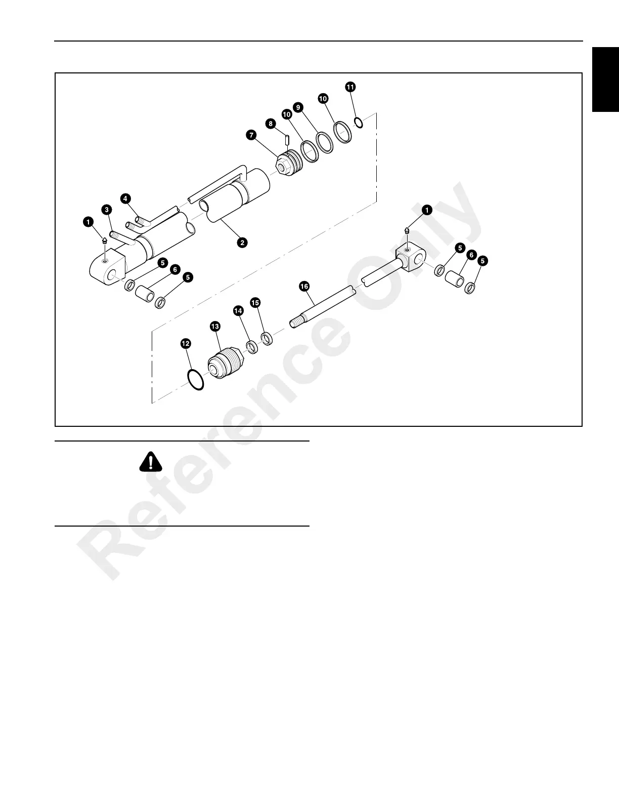
4. Fasten the bushing end of the cylinder rod in a vice. Do
not clamp a vise on the cylinder rod.
5. Remove and discard piston seal 9 and wear rings 10
from piston 7.
6. Remove dowel 8 from piston head 7 using a metric
screw threaded into the extraction hole in the dowel.
7. Using a special spanner wrench (See Special Tools on
page 10-24) remove the piston 7 from rod 16.
8. Remove and discard O-ring 11.
9. Remove cap end 13 from cylinder rod 16.
10. Remove and discard O-ring 12, seal gland 14 and wiper
seal 15 from cap end 13.
11. Remove and discard the oil seals 5 from both the rod
end and base ends of the cylinder.
Inspection
1. Clean all parts in a suitable solvent. Dry with
compressed air. Make sure threads of piston rod, piston,
end cap and cylinder are thoroughly cleaned using a
wire brush to remove grease, hydraulic oil and Loctite.
2. Inspect cylinder rod for rust, distortion, pitting or damage
to the chrome. If there is damage to the cylinder rod,
replace it. Do not try to straighten a bent cylinder rod.
3. Inspect inside of the cylinder barrel for grooves,
distortion or other damage. Use a light to illuminate the
cylinder bore for careful inspection. Replace any
cylinder barrel if there is distortion or damage.
4. Inspect the piston for damage to the lands.
5. Inspect rod and barrel bushings for wear or damage.
6. Replace all seals and rings.
FIGURE 10-65
a0342
1. Grease Fitting (2)
2. Cylinder Barrel
3. Left Side Pipe
4. Right Side Pipe
5. Oil Seal (4)
6. Bushing (2)
8. Dowel
8. Piston
9. Piston Seal
10. Wear Ring
11. O-Ring
12. O-Ring
13. End Cap
14. Gland Seal
15. Wiper Seal
16. Cylinder Rod
CAUTION
If air or hydraulic pressure is used to force out the piston
assembly, ensure that the end cap is securely installed.
Severe injury can be caused by a sudden release of the
piston rod.
Reference Only
 Loading...


