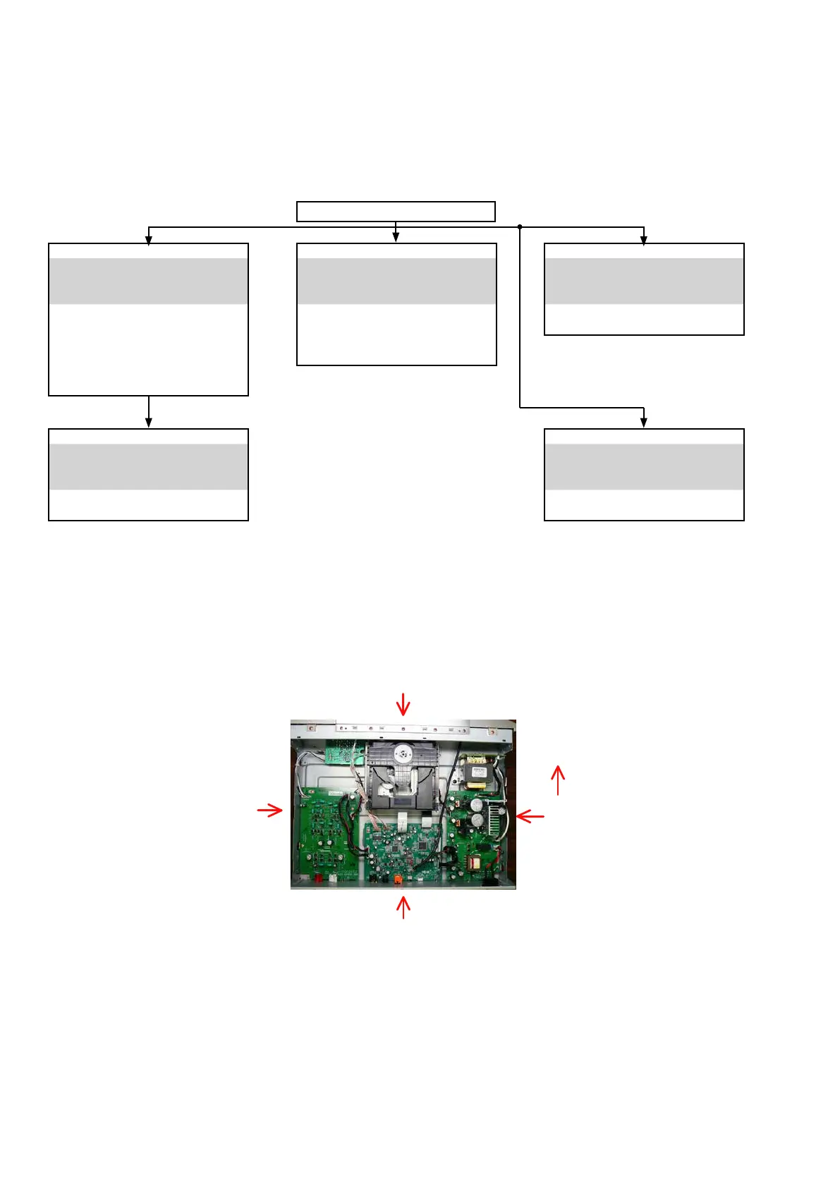
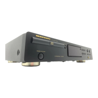
About the photos used for "descriptions of the DISASSEMBLY" section
• The shooting direction of each photograph used herein is indicated on the left side of the respective photograph as
"
Shooting direction: ***
"
.
• Refer to the diagram below about the shooting direction of each photograph.
• Photographs with no shooting direction indicated were taken from the top of the set.
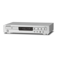
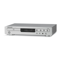
The viewpoint of each photograph
(Shooting direction X)
[View from the top]
Front side
Shooting direction: B
Shooting direction: D
Shooting direction: C
Shooting direction: A
CD MAIN P.W.B
Refer to
"DISASSEMBLY
2. CD MAIN P.W.B"
and
"EXPLODED VIEW"
CD MAIN P.W.B
(Ref. No. of EXPLODED VIEW : C7)
FLASHER PWB (U model only)
(Ref. No. of EXPLODED VIEW : M10)
POWER PWB
Refer to
"DISASSEMBLY
3. POWER PWB"
and
"EXPLODED VIEW"
POWER PWB
(Ref. No. of EXPLODED VIEW : C8)
MECHA ASSY
Refer to
"DISASSEMBLY
5. MECHA ASSY"
and
"EXPLODED VIEW"
CD MECHANISM ASS'Y
(Ref. No. of EXPLODED VIEW : C5)
AUDIO OUTPUT PWB
Refer to
"DISASSEMBLY
4. AUDIO OUTPUT PWB"
and
"EXPLODED VIEW"
AUDIO OUTPUT PWB
(Ref. No. of EXPLODED VIEW : C6)
FRONT PANEL ASSY
Refer to
"DISASSEMBLY
1. FRONT PANEL ASSY"
and
"EXPLODED VIEW"
FRONT PWB
(Ref. No. of EXPLODED VIEW : C1)
STBY SW PWB
(Ref. No. of EXPLODED VIEW : C2)
EARPHONE PWB
(Ref. No. of EXPLODED VIEW : C3)
TOP COVER
DISASSEMBLY
• Disassemble in order of the arrow in the following gure.
• In the case of the re-assembling, assemble it in order of the reverse of the following ow.
• In the case of the re-assembling, observe "attention of assembling".
• If wire bundles are untied or moved to perform adjustment or replace parts etc., be sure to rearrange them neatly as
they were originally bundled or placed afterward.
Otherwise, incorrect arrangement can be a cause of noise generation.
12