Proceeding : TOP COVER → SIDE PANEL → AUDIO IN PCB → RCA PCB
(1) Remove the screws. Remove the connector. Remove the STYLE PIN.
NOTE : Take care with the placement of the wires from the POWER PCB when assembling.
Proceeding : TOP COVER → SIDE PANEL → AUDIO IN PCB → RCA PCB → POWER PCB
(1) Remove the screws. Remove the connector.
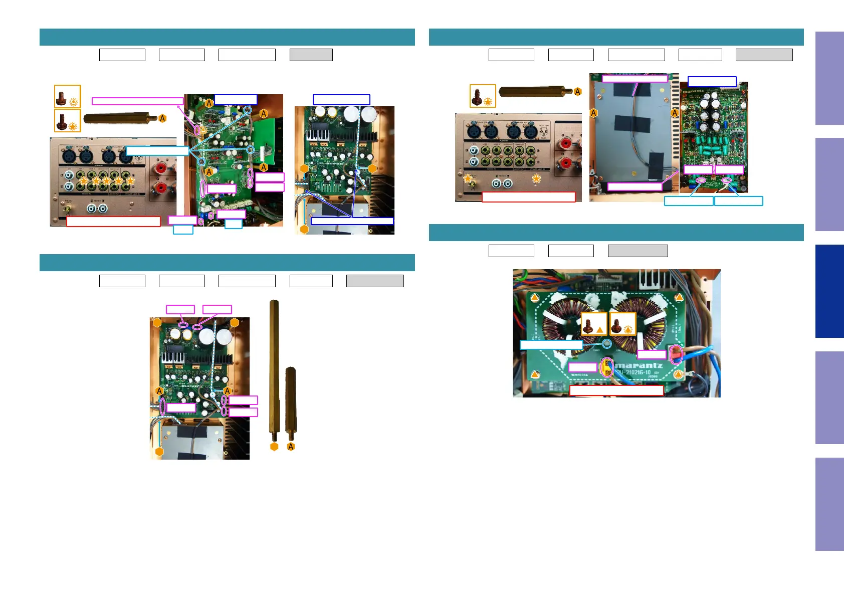
4. RCA PCB
↑Shooting direction: A↑
x5
x4
N2005
N2006
N2501
N2503
x1
N2001
Rch
Lch
STYLE PIN x3
To POWER PCB Z5003 or Z5004
Place the wire in this position.
POWER PCBRCA PCB
5. POWER PCB
x2x2
B
B B
N8104
N8101
N8103
N8100N8102
Proceeding : TOP COVER → SIDE PANEL → AUDIO IN PCB → RCA PCB → PHONO ASSY
(1) Remove the screws. Remove the connector.
Proceeding : TOP COVER → SIDE PANEL → INDUCTOR PCB
(1) Remove the screws. Remove the connector. Remove the PCB HOLDER.
6. PHONO ASSY
↑Shooting direction: A↑
PONO PCB
x2
x2
N4004 N4005
PONO RchPONO Lch
To SPK PCB Z9506
To POWER PCB N8104
7. INDUCTOR PCB
↑Shooting direction: A↑
x1x3
N8803
N8801
PCB HOLDER
41
Caution in
servicing
Electrical Mechanical Repair Information Updating
 Loading...