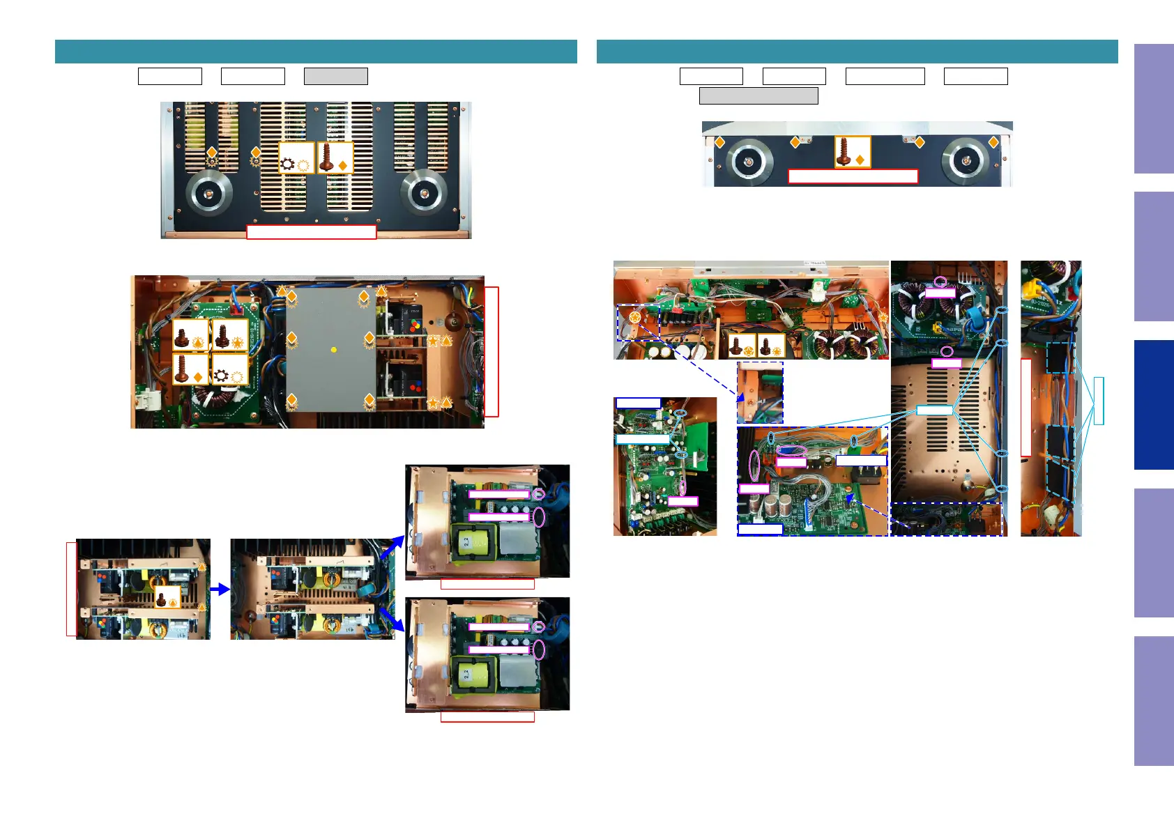
Proceeding : TOP COVER → SIDE PANEL → SMPS ASSY
(1) Remove the screws.
(2) Remove the screws.
(3) Remove the screws. Remove the connector.
2. SMPS ASSY
View from the bottom
x2x2
↑Shooting direction: A↑
x4
x6 x6
x2
↓Shooting direction: A↓
↑Shooting direction: D↑
↑Shooting direction: D↑
x2
To AMP ASSY N8506
To AC PCB N8506
To AMP ASSY N6004
To AC PCB N8505
Proceeding : TOP COVER → SIDE PANEL → AUDIO IN PCB → SMPS ASSY
→ FRONT PANEL ASSY
(1) Remove the screws.
(2) Remove the screws. Remove the connector. Remove the STYLE PIN.
Cut the wire clamps. Remove the SHEET.
NOTE : Use a new sheet when assembling.
3. FRONT PANEL ASSY
View from the bottom
x4
View from the inside
x1x1
CUT x6
N8503
N1901
N9505
SHEET x3
RCA PCB
N2503
STYLE PIN
SPK PCB
N8507
FCBS PCB
40
Caution in
servicing
Electrical Mechanical Repair Information Updating
 Loading...