Proceeding : TOP COVER → SIDE PANEL → INDUCTOR PCB → AC PCB
(1) Remove the screws. Remove the connector.
Proceeding : TOP COVER → POWER TRANS
(1) Remove the screws. Remove the connector. Remove the CORD HOLDER.
Cut the wire clamps.
8. AC PCB
↑Shooting direction: A↑
x4
N8504
N8503
N8509
N8507
N8508
N8501
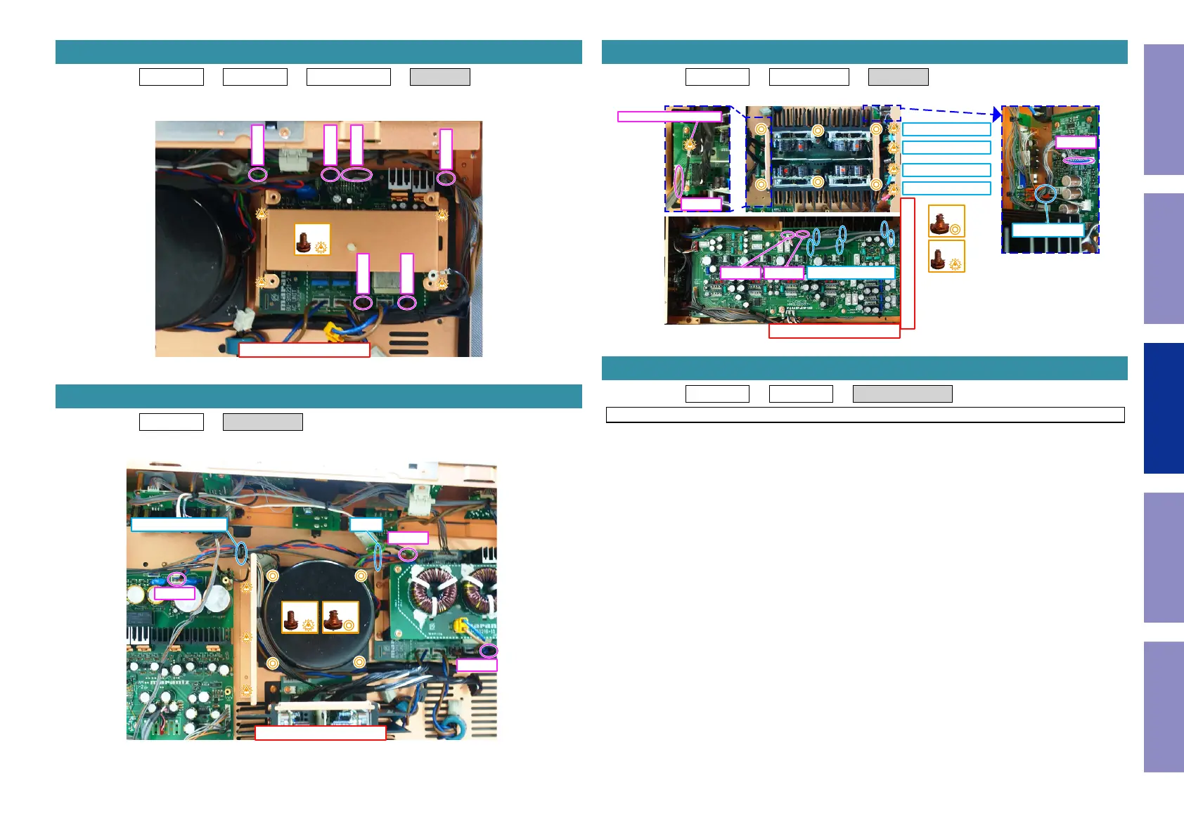
9. POWER TRANS
↑Shooting direction: A↑
x4x3
N8504
N8501
N8100
CUTCORD HOLDER
Proceeding : TOP COVER → POWER TRANS → AMP ASSY
(1) Remove the screws. Remove the connector. Remove the STYLE PIN.
Proceeding : TOP COVER → SIDE PANEL → REAR PANEL ASSY
See "EXPLODED VIEW" for instructions on removing the REAR PANEL ASSY.
10. AMP ASSY
↑Shooting direction: C↑
↑Shooting direction: A↑
x6
x5
N5010 N5009
STYLE PIN x6
AMP Lch RED
AMP Lch BLU
AMP Rch BLU
AMP Rch RED
N9504
STYLE PIN
N6007
from POWER PCB B8102
11. REAR PANEL ASSY
42
Caution in
servicing
Electrical Mechanical Repair Information Updating
 Loading...