42
SERIAL
DATA
INTERFACE
8 x Fs
INTERPOLATOR
SERIAL CONTROL
INTERFACE
AUTO-CLOCK
DIVIDE CIRCUIT
VOLUME
MUTE
CONTROL DATA
INPUT
3
2
DIGITAL
SUPPLY
CLOCK
IN
ANALOG
OUTPUTS
22
ZERO
FLAG
ANALOG
SUPPLY
DE-EMPHASISMUTE
2
SERIAL
MODE
DIGITAL
DATA INPUT
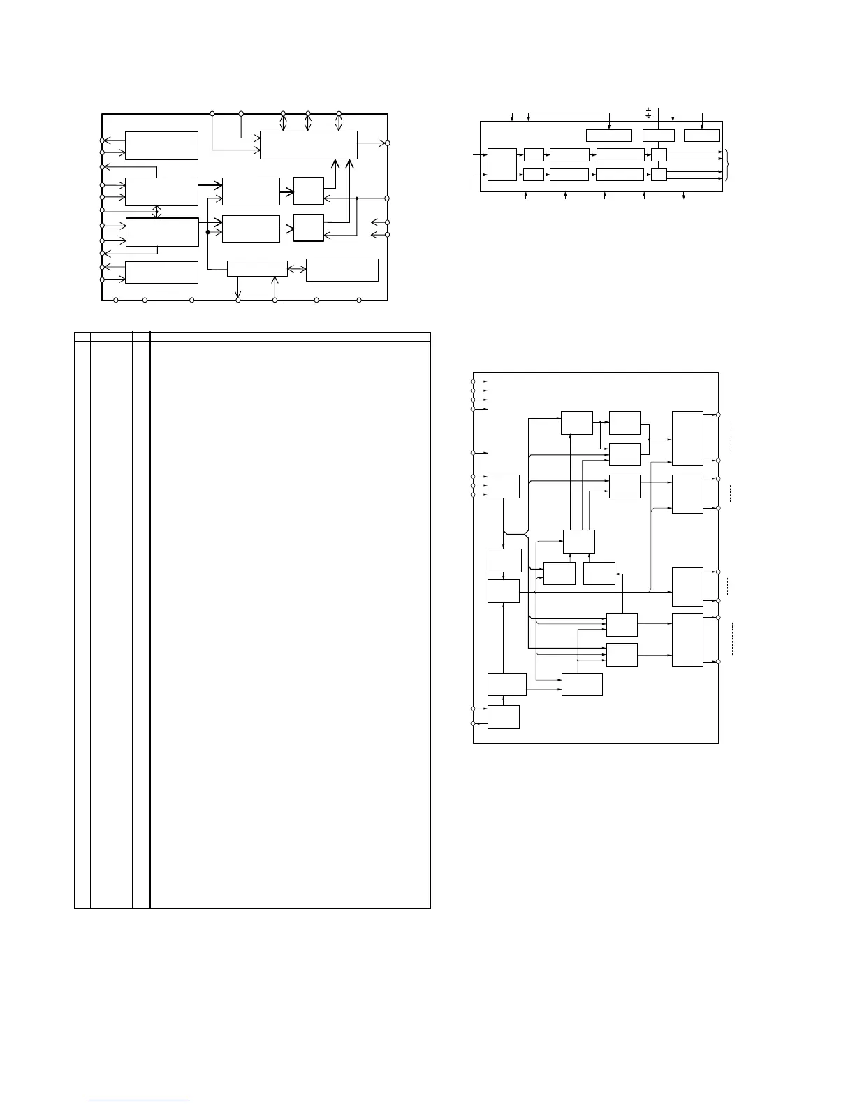
AD1853
MULTIBIT SIGMA-
DELTA MODULATOR
ATTEN/
MUTE
IDAC
MULTIBIT SIGMA-
DELTA MODULATOR
8 x Fs
INTERPOLATOR
ATTEN/
MUTE
VOLTAGE
REFERENCE
IDAC
INT2 x INT4 x
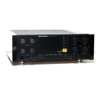
RESET
DCRAM
24w L8b
CGROM
240w x 35b
CGRAM
16w x 35b
ADRAM
24w x 4b
8-bit
Shift
Register
Command
Decoder
Control
Circuit
Timing
Generator1
Oscillator
Timing
Generator2
Digit
Control
Duty
Control
Grid
Driver
Port
Driver
AD
Driver
Segment
Driver
Write
Address
Counter
Read
Address
Counter
Address
Selector
SEG1
SEG35
AD1
AD4
VDISP
VDD
GND
VFL
RESET
DA
CP
CS
OSC0
OSC1
P1
P4
COM1
COM24
QD01 : AD1853
QU02 : ML9205-01GA
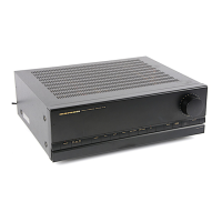
LRCK
VREFL
GNDL
SCLKSMODE1
FSYNC
Serial Output
Interface
SMODE2
DGNDVA
AGND
BGND
CAL
RST
VD
Controller
SDATA
MCLK
DFS
HPFE
ZCAL
AINR-
GNDR
Delta-Sigma
Modulator
Delta-Sigma
Modulator
Voltage
Reference
Voltage
Reference
Decimation
Filter
Decimation
Filter
HPF
HPF
Calibration
SRAM
VCOML
AINL+
AINL-
AINR+
VCOMR
VREFR
12 11 14 13
16
15
19
17
18
87
109
212223
27
28
26
24
25
6
5
4
3
2
1
No. Pin Name I/O Func tion
1 VREFL O
Lc h Ref erence Voltage Pin, 3.75V
Norm ally conne cted to GNDL w ith a 10µF electrol ytic capacitor and a 0.1µF
ceram ic capacitor.
2 GNDL - Lch Reference Ground Pin, 0V
3 VCOML O Lch Common V oltage Pin, 2.75V
4 AINL+ I Lc h A nal og posi tive input Pin
5 AINL- I Lc h A nal og negat ive input Pin
6 ZCAL I
Zero Cal ibrat ion Cont rol Pin
This pi n c ont rol s the c alibrat ion ref erenc e si gnal .
" L" : VCOML and VCOMR
" H" : Anal og Input Pins (AINL+-, AINR+-)
7 VD - Digi tal Power Suppl y Pin, 3.3V
8 DGND - Digi tal Ground Pin, 0V
9 CAL O Calibrat ion A ctive Signal Pin
" H" means the o ffset calibrat ion cyc le is in progress . Offset calibrat ion st art s
when RS T goes "H". CAL goe s "L" after 8704 LRCK cycles for DFS="L" ,
17408 LRCK cyc les for DFS =" H" .
10 RST I
Reset Pin
When " L" , Digital sect ion is powered-down. Upon ret urni ng " H", an of fset
calibrat ion cyc le is st art ed. An of fset calibrat ion cyc le shoul d always be
initiated after power-up.
11 SMODE2 I Seri al Interface Mode Select Pin
12 SMODE1 I
MSB first, 2's compliment.
SMODE2 SMODE1 MODE LRCK
L L Slave mode : MSB justified : H/L
L H Master mode : Similar t o
2
I S : H/L
H L Slave mode : I S : L/H
2
H H Master m ode : I S : L/H
2
13 LRCK I/O
Left/R igh t Channel Select Cloc k Pin
LRCK goes " H" at SMODE2=" L" and " L" at SMODE2=" H" duri ng reset when
SMODE1 "H" .
14 SCLK I/O
Seri al Data Clock P in
Data is clocked ou t on the falling edge of SCLK .
Slave mode: SCLK requi res m ore than 48f s clock.
Mast er m ode: SCLK output s a 128fs(DFS="L" ) or 64f s(DFS=" H" ) clock.
SCLK stays "L" duri ng reset.
15 SDATA O
Serial Data Outp ut Pin
MSB first , 2's complement. SDATA stays " L" duri ng res et.
16 FSYNC I/O
Fram e Synchroni zation S ignal Pin
Slave mode: When " H" , the da ta bits are clock ed ou t on SDATA. In I
2
S mode ,
FSYNC is Don’t care.
Mast er m ode: FSYNC output s 2fs clock. FSYNC st ays " L" duri ng reset .
17 MCLK I
Mast er Cl ock I nput Pin
256fs at DFS=" L" , 128fs at DFS=" H" .
18 DFS I
Doubl e Speed Sampling Mode Pin
" L" : Norm al Speed
" H" : Doubl e Speed
19 HPFE I
High P ass Filter Enabl e Pin
" L" : Disable
" H" : Enabl e
20 TEST I Test Pin ( pul l-down pi n) Shoul d be connect ed to GND.
21 BGND - Subst rate Ground Pin, 0V
22 AGND - Anal og Ground Pin, 0V
23 VA - Anal og S uppl y Pin, 5V
24 AINR- I Rch A nalog negat ive inpu t Pin
25 AINR+ I Rch A nalog posi tive inpu t Pin
26 VCOMR O Rch Common Voltage Pin, 2.75V
27 GNDR - Rch Ref erenc e Ground P in, 0V
28 VREFR O
Rch Ref erenc e Voltage Pin, 3.75V
Norm ally conne cted to GNDR wi th a 10µF elect rol yt ic capac itor and a 0.1µF
ceram ic capacitor
QK01 : AK5383