6
Channel
Measuremet
Point Point
Surround Left CN63 VR83 or VR8x
Center CN61 VR81 or VR8x
Surround Right CN65 VR85 or VR8x
Front Left CN67 VR87 or VR8x
Surroud Back Left CN62 VR82 or VR8x
Front
Right
CN66 VR86 or VR8x
After Turning ON
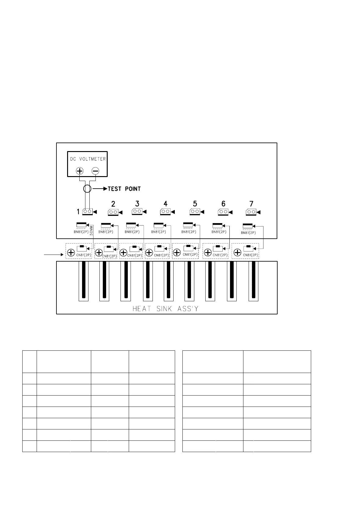
Time Table of Idling Current Rise DC voltmeter........Connect to CN6x
Measurement Voltage
12.0 mV ±
0.5 mV
13.0 mV ±
0.5 mV
13.0 mV ±
0.5 mV
13.2 mV ±
0.5 mV
13.4 mV ±
0.5 mV
13.5 mV ±
0.5 mV
(CN6x)
Alignment
10 min
20 min
30 min
40 min
50 min
5 min
Surroud Back Right
No.
1
2
3
4
5
6
7
CN64 VR84 or VR8x 13.5 mV ±
0.5 mV 60 min
MAIN PWB
CUP11888
TR BIAS
PWB
CN63(2p) CN61(2p) CN65(2p) CN67(2p) CN62(2p) CN66(2p) CN64(2p)
VR83 or
VR8x
VR81 or
VR8x
VR85 or
VR8x
VR87 or
VR8x
VR82 or
VR8x
VR86 or
VR8x
VR84 or
VR8x
3. POWER AMPLIFIER ADJUSTMENT
Idling Current Alignment
1. Each of the measurement points are provided with the two test points. Set a digital Voltage meter to DC voltage input,
connect the meter to the test points at both contact points.
2. After the setup above, turn on the main switch.
3. Adjust variable resistors (VR81 - VR87) according to the digital voltmeter readings. The target setting value is the
following table for each channels.
Settings :
Master Volume — Minimum
Speaker out — No Load
Top lid — OPEN