7
S E R V I C E M O D E
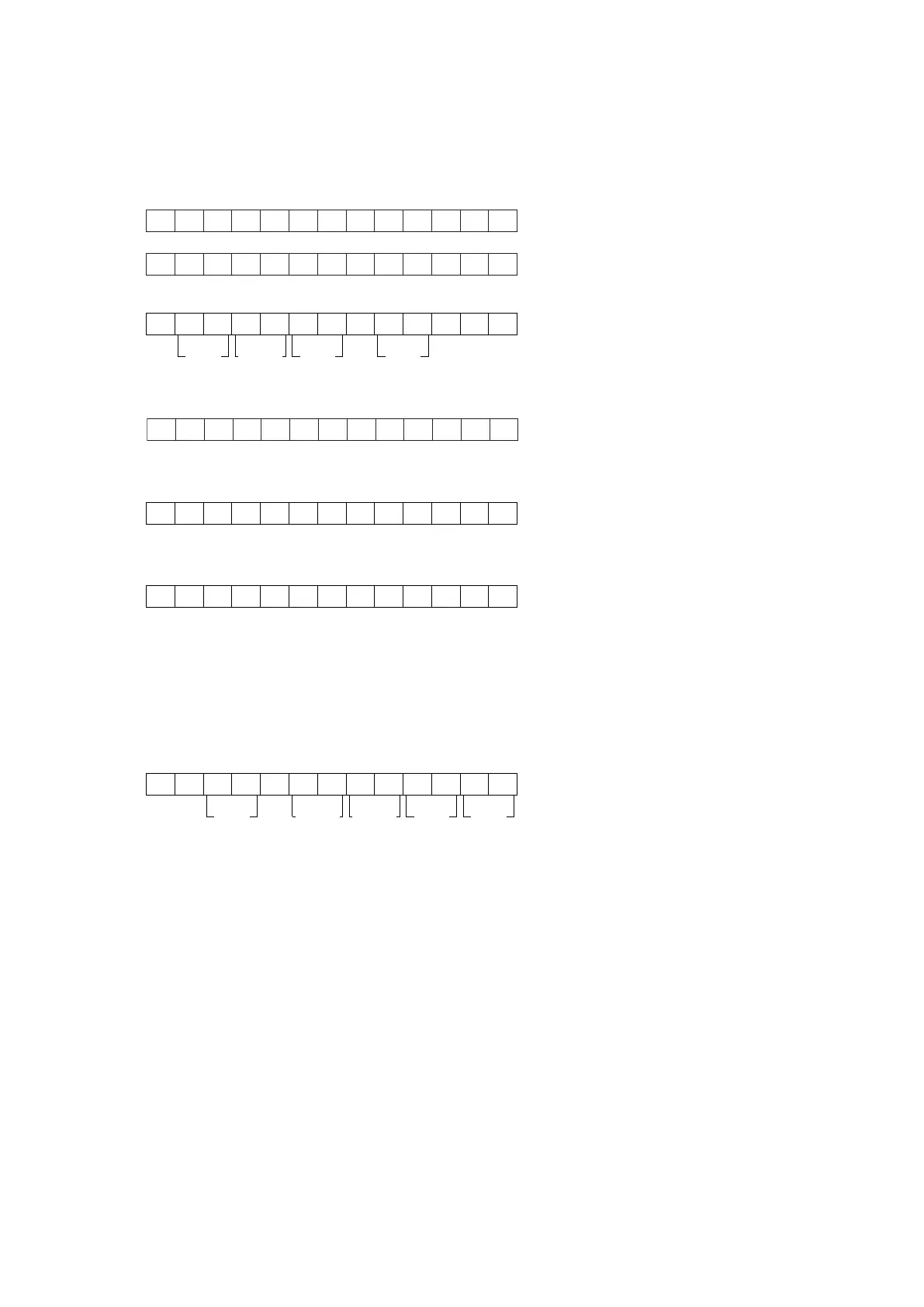
S R 4 0 0 1
V 0 6 0 4 1 7 1 U
Month Date Dest.
(Dest. : Destination)
Year
S O F T T Y P E X X
(XX is displayed in Hex)
C O D E T Y P E X X X X
(XXXX is displayed in Hex)
C D 0 1 0 2 0 6 0 1 0 5
SIG
Dev. TYP Ver.No.
No. : DISP CODE ID Dev. : Device ID SIG. : CODE SIG ID
TYP. : CODE TYPE ID Ver. : Version
M Z X X X X X X X X X
(XX is displayed in Hex)
4. SERVICE MODE
Microprocessor (IC11), DSP ROM(IC40 )Version and FLD Segment Check Mode.
1. While the power is on, ATT, EXIT and 7.1CH INPUT buttons simultaneously more than 3 seconds.
The FL display shows "SERVICE MODE" for 2 seconds then shows the model name.
2. Press 7.1CH INPUT button, The software version of the microprocessor (IC11) is displayed in the format below.
3. Press 7.1CH INPUT button again, The software Serial Number that is written in the factory is displayed.
4. Press 7.1CH INPUT button again, The software Type Number is displayed.
5. Press 7.1CH INPUT button again, The Code Group Type Number is displayed.
6. Press 7.1CH INPUT button again, The left half, right half and center of the label area in the FLD light on and off each
other.
7. Press 7.1CH INPUT button again, The segments of the character area in the FLD flick in checker pattern.
8. Press 7.1CH INPUT button again, All the FL segments turns off.
9. Press 7.1CH INPUT button again. Every time 7.1CH INPUT button is pressed, DSP code is indicated in turn from NO.1
to NO.10.
10. Press 7.1CH INPUT button again to quit this mode.
Note :
Step4, 5 is to check if CPU software is capable of DSP code. "Software Type No" is to show what "DSP Code Group" CPU is
capable of. And vice versa.
Step 9 is to manage the 16 codes for DSP.
• When the unit is once turned into Service Mode, the unit keeps this mode until the main power is turned off. (Turning
into stand-by mode does not make it quit from Service Mode.) When the unit quits from Service Mode, Information in the
memory is also cleared and the unit returns to the status when it is out from the factory.
Product Reset
To reset the back up memory of the unit into the default status, follow the procedure below.
1. Turn of the unit and press ATT and 7.1CH INPUT button simultaneously more than 1.5 seconds.
2. After "DEFAULT" is displayed on FLD, power is turned off once and turned of again, EEPROM is cleared to the default
status, microprocessor is reset and the unit returns to the normal status.
Note :
When the unit is shipped from the factory, the procedure above must be done to set the unit to initial status after the
tests.