ADV7403
Rev. SpA | Page 11 of 24
Pin No. Mnemonic Type Function
3
INT
O
Interrupt. This pin can be active low or active high. When SDP/CP status bits change,
this pin triggers. The set of events that triggers an interrupt is under user control.
4 HS/CS O
HS is a Horizontal Synchronization Output Signal (SDP and CP modes). CS is a Digital
Composite Synchronization Signal (and can be selected while in CP mode).
99 VS O Vertical Synchronization Output Signal (SDP and CP modes).
98 FIELD/DE O
FIELD is a Field Synchronization Output Signal (all interlaced video modes). This
pin also can be enabled as a Data Enable signal (DE) in CP mode to allow direct
connection to a HDMI/DVI Tx IC.
81, 19 SDA1, SDA2 I/O
I
2
C Port Serial Data Input/Output Pins. SDA1 is the data line for the control port, and
SDA2 is the data line for the VBI readback port.
82, 16 SCLK1, SCLK2 I
I
2
C Port Serial Clock Input (max clock rate of 400 kHz). SCLK1 is the clock line for the
Control port and SCLK2 is the clock line for the VBI data readback port.
80 ALSB I
This pin selects the I
2
C address for the ADV7403 control and VBI readback ports. ALSB
set to Logic 0 sets the address for a write to control port of 0x40 and the readback
address for the VBI port of 0x21. ALSB set to a logic high sets the address for a write to
control port of 0x42 and the readback address for the VBI port of 0x23.
78
RESET
I
System Reset Input. Active low. A minimum low reset pulse width of 5 ms is required
to reset the ADV7403 circuitry.
36 LLC1 O
LLC1 is a line-locked output clock for the pixel data (range is 12.825 MHz to 140 MHz
for ADV7403KSTZ-140; 12.825 MHz to 110 MHz for ADV7403BSTZ-110.
38 XTAL I
Input Pin for 28.63636 MHz crystal, or can be overdriven by an external 3.3 V,
28.63636 MHz clock oscillator source to clock the ADV7403.
37 XTAL1 O
This pin should be connected to the 28.63636 MHz crystal or left as a no connect if an
external 3.3 V 28.63636 MHz clock oscillator source is used to clock the ADV7403. In
crystal mode the crystal must be a fundamental crystal.
46 ELPF O The recommend external loop filter must be connected to this ELPF pin.
70 TEST0 NC This pin should be left unconnected or alternaltely tie to AGND.
59 TEST1 O This pin should be left unconnected.
15 SFL/SYNC_OUT O
Subcarrier Frequency Lock (SFL). This pin contains a serial output stream, which can
be used to lock the subcarrier frequency when this decoder is connected to any
Analog Devices digital video encoder. SYNC_OUT is the sliced sync output signal
available only in CP mode.
64 REFOUT O Internal Voltage Reference Output.
65 CML O Common-Mode Level Pin (CML) for the internal ADCs.
61, 62 CAPY1, CAPY2 I ADC Capacitor Network.
68, 69 CAPC1, CAPC2 I ADC Capacitor Network.
67 BIAS O
External Bias Setting Pin. Connect the recommended resistor (1.35 kΩ) between pin
and ground.
86 HS_IN/CS_IN I
Can be configured in CP mode to be either a digital HS input signal or a digital CS
input signal used to extract timing in a 5-wire or 4-wire RGB mode.
85 VS_IN I VS Input Signal. Used in CP mode for 5-wire timing mode.
79 DE_IN I
Data Enable Input Signal. Used in 24-bit digital input port mode (for example,
processing 24-bit RGB data from a DVI Rx IC).
35 DCLK_IN I
Clock Input Signal. Used in 24-bit digital input mode (for example, processing 24-bit
RGB data from a DVI Rx IC) and also in digital CVBS input mode.
52 SOG I Sync on Green Input. Used in embedded sync mode.
77 SOY I Sync on Luma Input. Used in embedded sync mode.
ADV7403
Rev. SpA | Page 10 of 24
PIN CONFIGURATION AND FUNCTION DESCRIPTIONS
26
P6
27
P5
28
P4
29
P26
30
P25
31
P24
32
P23
33
P22
34
P21
35
DCLK_IN
36
LLC1
37
XTAL1
38
XTAL
39
DVDD
2
3
4
7
6
5
1
8
9
10
12
13
14
15
16
17
18
19
20
21
22
23
24
25
11
74
73
72
69
70
71
75
68
67
66
64
63
62
61
60
59
58
57
56
55
54
53
52
51
65
40
DGND
41
P3
42
P2
43
P1
44
P0
45
P20
46
ELPF
47
PVDD
48
PVDD
49
AGND
50
AGND
05431-002
100
99
98
97
96
95
94
93
92
91
90
89
88
87
86
85
84
83
82
81
80
79
78
77
76
PIN 1
ADV7403
LQFP
TOP VIEW
(Not to Scale)
P11
P32
P31
INT
CS/HS
DGND
DVDDIO
P15
P14
P13
P12
DGND
DVDD
P29
P28
SFL/SYNC_OUT
SCLK2
DGND
DVDDIO
SDA2
P10
P9
P8
P27
P7
AIN2
AIN8
AIN1
AIN7
SOG
AIN9
AIN3
TEST1
AGND
CAPY1
CAPY2
AVDD
REFOUT
CML
AGND
BIAS
CAPC1
CAPC2
TEST0
AIN10
AIN4
AIN11
AIN5
AIN12
FB
F
I
E
L
D
/
D
E
D
E
_
I
N
S
O
Y
A
I
N
6
A
L
S
B
S
D
A
1
S
C
L
K
1
P
4
0
P
3
9
V
S
_
I
N
H
S
_
I
N
/
C
S
_
I
N
P
3
8
P
3
7
D
G
N
D
D
V
D
D
P
1
9
P
1
7
P
1
6
P
3
6
P
3
5
P
3
4
V
S
P
3
3
P
1
8
R
E
S
E
T
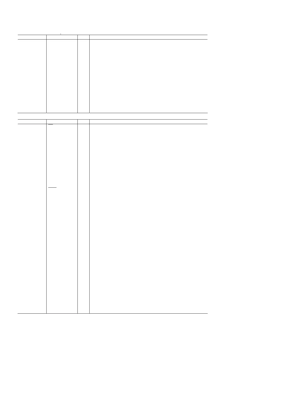
Figure 2. Pin Configuration
Table 7. Pin Function Descriptions
Pin No. Mnemonic Type Function
5, 11, 17, 40, 89 DGND G Digital Ground.
49, 50, 60, 66 AGND G Analog Ground.
6, 18 DVDDIO P Digital I/O Supply Voltage (3.3 V).
12, 39, 90 DVDD P Digital Core Supply Voltage (1.8 V).
63 AVDD P Analog Supply Voltage (3.3 V).
47, 48 PVDD P PLL Supply Voltage (1.8 V).
51 FB I Fast Switch Overlay Input. This pin switches between CVBS and RGB analog signals.
54, 56, 58, 72, 74,
76, 53, 55, 57, 71,
73, 75
AIN1 to AIN12 I Analog Video Input Channels.
42, 41, 28, 27, 26,
25, 23, 22, 10, 9, 8,
7, 94, 93, 92, 91
P2 to P9, P12 to P19 O Video Pixel Output Port.
44, 43, 21, 20, 45,
34, 33, 32, 31, 30,
29, 24, 14, 13
P0 to P1, P10 to P11,
P20 to P21, P22 to
P25, P26 to P29
I/O Video Pixel Input/Output Port.
2, 1, 100, 97, 96,
95, 88, 87, 84, 83
P31 to P40 I Video Pixel Input Port.
 Loading...