Semiconductor Components Industries, LLC, 2006
March, 2006 − Rev. 0
1 Publication Order Number:
NB3N502/D
NB3N502
14 MHz to 190 MHz PLL
Clock Multiplier
Description
The NB3N502 is a clock multiplier device that generates a low jitter,
TTL/CMOS level output clock which is a precise multiple of the
external input reference clock signal source. The device is a cost
efficient replacement for the crystal oscillators commonly used in
electronic systems. It accepts a standard fundamental mode crystal or
an external reference clock signal. Phase−Locked−Loop (PLL) design
techniques are used to produce an output clock up to 190 MHz with a
50% duty cycle. The NB3N502 can be programmed via two select
inputs (S0, S1) to provide an output clock (CLKOUT) at one of six
different multiples of the input frequency source, and at the same time
output the input aligned reference clock signal (REF).
Features
• Clock Output Frequency up to 190 MHz
• Operating Range: V
DD
= 3 V to 5.5 V
• Low Jitter Output of 15 ps One Sigma (rms)
• Zero ppm Clock Multiplication Error
• 45% − 55% Duty Cycle
• 25 mA TTL−level Drive Outputs
• Crystal Reference Input Range of 5 − 27 MHz
• Input Clock Frequency Range of 2 − 50 MHz
• Available in 8−pin SOIC Package or in Die Form
• Full Industrial Temperature Range −40°C to 85°C
• This is a Pb−Free Device
÷ M
Feedback
V
DD
Multiplier
Select
S1
Reference
Clock
REF
Phase
Detector
Charge
Pump
Crystal
Oscillator
X2
÷ P
X1/CLK
CLKOU
Figure 1. NB3N502 Logic Diagram
GND
S0
TTL/
CMOS
Output
VCO
TTL/
CMOS
Output
Device Package Shipping
†
ORDERING INFORMATION
NB3N502DG SOIC−8
(Pb−Free)
98 Units/Rail
SOIC−8
D SUFFIX
CASE 751
MARKING DIAGRAM
http://onsemi.com
1
8
3N502 = Specific Device Code
A = Assembly Location
L = Wafer Lot
Y = Year
W = Work Week
� = Pb−Free Package
3N502
ALYW
�
1
8
NB3N502DR2G SOIC−8
(Pb−Free)
2500/Tape & Reel
†For information on tape and reel specifications,
including part orientation and tape sizes, please
refer to our Tape and Reel Packaging Specification
Brochure, BRD8011/D.
NB3N502
http://onsemi.com
2
Figure 2. Pin Configuration (Top View)
CLKOUT
S0
S1
X2
X1/CLK
V
DD
GND
REF
1
2
3
45
6
7
8
Table 1. CLOCK MULTIPLIER SELECT TABLE
S1* S0** Multiplier
L L 2X
L H 5X
M L 3X
M H 3.33X
H L 4X
H H 2.5X
L = GND
H = V
DD
M = OPEN (unconnected)
* Pin S1 defaults to M when left open
** Pin S0 defaults to H when left open
Table 2. OUTPUT FREQUENCY EXAMPLES
Output Frequency (MHz) 20 25 33.3 48 50 54 64 66.66 75 100 108 120 135
Input Frequency (MHz) 10 10 10 16 20 13.5 16 20 15 20 27 24 27
S1, S0 0 ,0 1, 1 M, 1 M, 0 1, 1 1, 0 1, 0 M, 1 0, 1 0, 1 1, 0 0, 1 0, 1
Table 3. PIN DESCRIPTION
Pin # Name I/O Description
1 X1/CLK Input Crystal or External Reference Clock Input
2 V
DD
Power Supply Positive Supply Voltage (3 V to 5.5 V)
3 GND Power Supply 0 V Ground.
4 REF CMOS/TTL Output Buffered Crystal Oscillator Clock Output
5 CLKOUT CMOS/TTL Output Clock Output
6 S0 CMOS/TTL Input Multiplier Select Pin − Connect to V
DD
or GND. Internal Pull−up Resistor.
7 S1 Three−level Input Multiplier Select Pin − Connect to V
DD
, GND or Float to M.
8 X2 Crystal Input Crystal Input − Do Not Connect when Providing an External Clock Reference
Table 4. ATTRIBUTES
Characteristic Value
ESD Protection Human Body Model
Machine Model
> 8 kV
> 600 V
Moisture Sensitivity, Indefinite Time Out of Drypack (Note 1) Level 1
Flammability Rating Oxygen Index: 28 to 34 UL 94 V−0 @ 0.125 in
Transistor Count 6700 Devices
Meets or Exceeds JEDEC Standard EIA/JESD78 IC Latchup Test
1. For additional Moisture Sensitivity information, refer to Application Note AND8003/D.
IC44 : TC7MBL6125
TC7MBL6125S,6126SFT/FK/FTG
2007-10-19
2
V
CC
9
B1
B2
8
14
13
12
11
10
1
2
3
4
5
6
7
A3
A4
GND
B3
B4
A1
A2
1OE
4OE
2OE
3OE
Pin Assignment (top view)
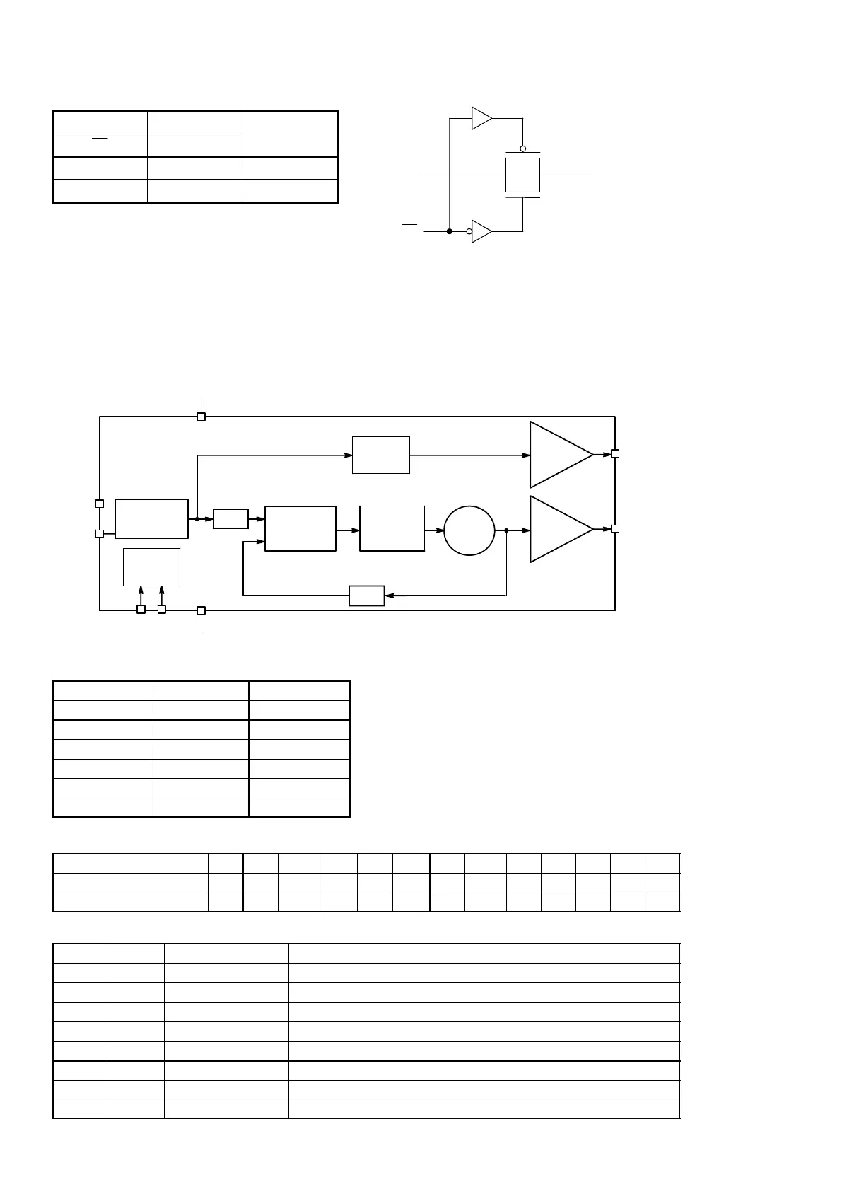
Truth Table
Inputs (6125S) Inputs (6126S)
OE
OE
Function
L H A port B port
H L Disconnect
System Diagram
FT (TSSOP14-P-0044-0.65A)
FK (VSSOP14-P-0030-0.50)
FTG (VQON16-P-0303-0.50)
1
2
3
4
4
16 15 14 13
NC V
CC
O E2
5 6 7 8
GND NC
12
11
10
9
B2
B3
B4
B1
O E1
O E4
O E3
V
CC
9
B1
B2
8
14
13
12
11
10
1
2
3
4
5
6
A3
A4
GND
B3
B4
A1
A2
OE1
O E4
O E3
O E2
FT (TSSOP14-P-0044-0.65A)
FK (VSSOP14-P-0030-0.50)
FTG (VQON16-P-0303-0.50)
1
2
3
4
4
16 15 14 13
NC V
CC
5 6 7 8
GND NC
12
11
10
9
B2
B3
B4
B1
1OE
4OE 3OE
2OE
TC7MBL6125S
TC7MBL6126S
O En
An Bn
An Bn
nOE
TC7MBL6125S
TC7MBL6126S
(n=1,2,3,4) (n=1,2,3,4)
TC7MBL6125S,6126SFT/FK/FTG
2007-10-19
2
V
CC
9
B1
B2
8
14
13
12
11
10
1
2
3
4
5
6
7
A3
A4
GND
B3
B4
A1
A2
1OE
4OE
2OE
3OE
Pin Assignment (top view)
Truth Table
Inputs (6125S) Inputs (6126S)
OE
OE
Function
L H A port B port
H L Disconnect
System Diagram
FT (TSSOP14-P-0044-0.65A)
FK (VSSOP14-P-0030-0.50)
FTG (VQON16-P-0303-0.50)
1
2
3
4
4
16 15 14 13
NC V
CC
O E2
5 6 7 8
GND NC
12
11
10
9
B2
B3
B4
B1
O E1
O E4
O E3
V
CC
9
B1
B2
8
14
13
12
11
10
1
2
3
4
5
6
A3
A4
GND
B3
B4
A1
A2
OE1
O E4
O E3
O E2
FT (TSSOP14-P-0044-0.65A)
FK (VSSOP14-P-0030-0.50)
FTG (VQON16-P-0303-0.50)
1
2
3
4
4
16 15 14 13
NC V
CC
5 6 7 8
GND NC
12
11
10
9
B2
B3
B4
B1
1OE
4OE 3OE
2OE
TC7MBL6125S
TC7MBL6126S
O En
An Bn
An Bn
nOE
TC7MBL6125S
TC7MBL6126S
(n=1,2,3,4) (n=1,2,3,4)
IC45 : NB3N502DR2G


 To Next Page