Copyright ¤ Cirrus Logic, Inc. 2006
(All Rights Reserved)
http://www.cirrus.com
Preliminary Product Information
This document contains information for a new product.
Cirrus Logic reserves the right to modify this product without notice.
192 kHz Stereo DAC with 2 Vrms Line Out
Features
Multi-bit Delta-Sigma Modulator
24-Bit Resolution
Supports Sample Rates up to 192 kHz
102 dB A-wt Dynamic Range
-90 dB THD+N
Integrated Line Driver
– 2 Vrms Output into 5 kΩ AC Load
– Analog Low-Pass Filter
Stereo Mutes with Auto-Mute Function
Low Clock-Jitter Sensitivity
Low-Latency Digital Filtering
Popguard
®
Technology for Control of Clicks
and Pops
Single-Ended Outputs
+3.3 Core, +9 to 12 Analog, and +1.5 to
3.3 Interface Power Supplies
Low Power Consumption
20-pin TSSOP, Lead-Free Assembly
Description
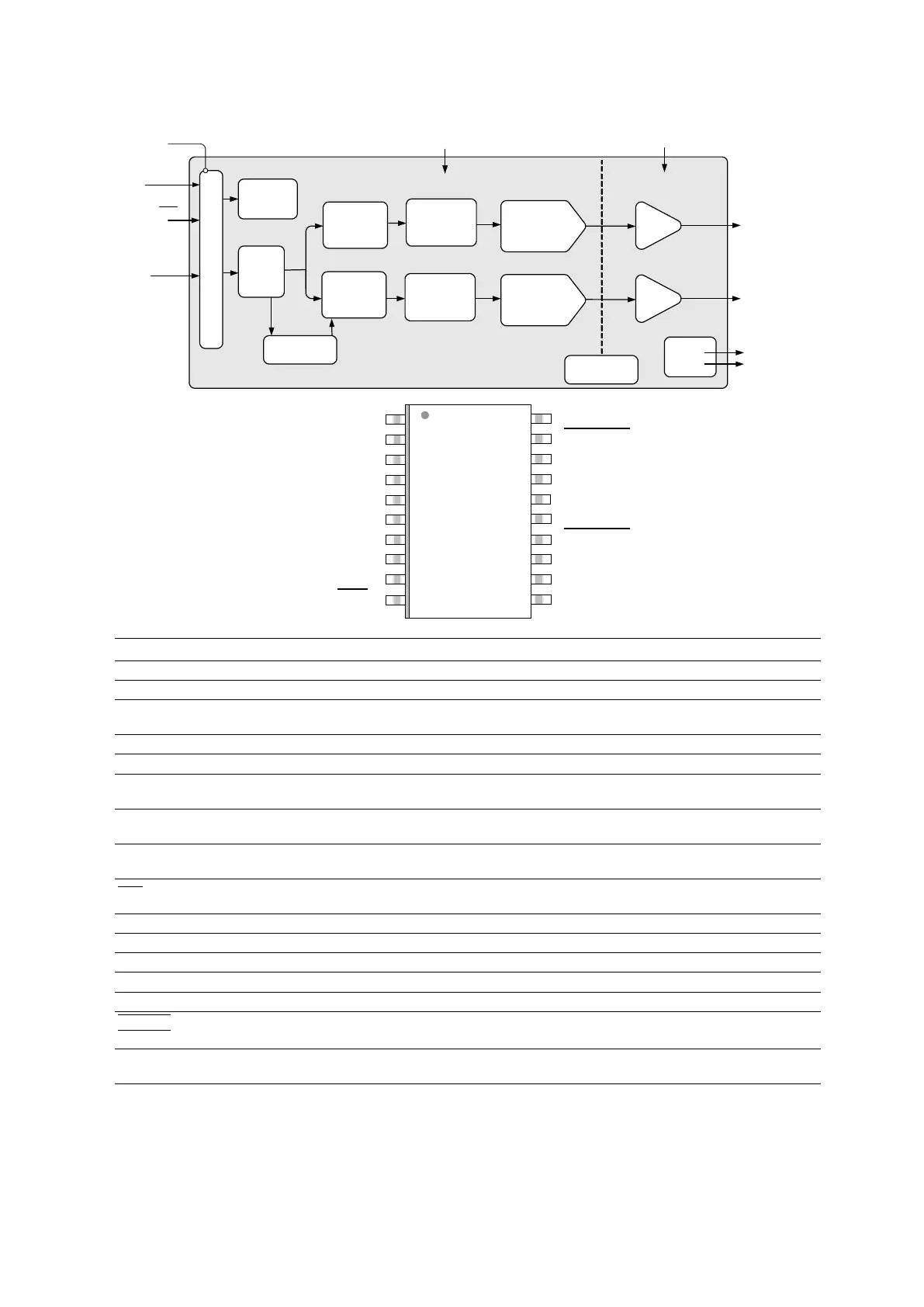
The CS4352 is a complete stereo digital-to-analog sys-
tem including digital interpolation, fifth-order multi-bit
delta-sigma digital-to-analog conversion, digital de-em-
phasis, analog filtering, and on-chip 2 Vrms line-level
driver. The advantages of this architecture include ideal
differential linearity, no distortion mechanisms due to re-
sistor matching errors, no linearity drift over time and
temperature, high tolerance to clock jitter, and a minimal
set of external components.
The CS4352 is available in a 20-pin TSSOP package in
Commercial (-10°C to +70°C) grade. The CDB4352
Customer Demonstration Board is also available for de-
vice evaluation and implementation suggestions.
Please see “Ordering Information” on page 19 for com-
plete details.
These features are ideal for cost-sensitive, 2-channel
audio systems including video game consoles, DVD
players, A/V receivers, set-top boxes, digital TVs and
DVD Recorders, mini-component systems, and mixing
consoles.
PCM
Serial
Interface
Interpolation
Filter
Serial Audio Input
Left and Right
Mute Controls
2 Vrms Line Level
Right Channel
Output
2 Vrms Line Level
Left Channel
Output
Reset
1.5 V to 3.3 V
Hardware
Configuration
Level Translator
Hardware Control
Multibit
∆Σ Modulator
3.3 V
9 V to 12 V
Interpolation
Filter
Amp
+
Filter
Amp
+
Filter
Multibit
∆Σ Modulator
Auto Speed Mode
Detect
DAC
DAC
External
Mute
Control
Internal Voltage
Reference
SEPTEMBER '06
DS684PP1
CS4352
DS684PP1 3
CS4352
1. PIN DESCRIPTION
Pin Name Pin # Pin Description
SDIN 1 Serial Audio Data Input (Input) - Input for two’s complement serial audio data.
SCLK 2
Serial Clock (Input) - Serial clock for the serial audio interface.
LRCK 3
Left / Right Clock (Input) - Determines which channel, Left or Right, is currently active on the serial
audio data line.
MCLK 4
Master Clock (Input) - Clock source for the delta-sigma modulator and digital filters.
VD 5
Digital Power (Input) - Positive power supply for the digital section.
GND
6
16
Ground (Input) - Ground reference.
DIF0
DIF1
8
7
Digital Interface Format (Input) - Defines the required relationship between the Left/Right Clock, Serial
Clock, and Serial Audio Data.
DEM 9
De-emphasis (Input) - Selects the standard 15 µs/50 µs digital de-emphasis filter response for 44.1 kHz
sample rates
RST
10
Reset (Input) - Powers down the device and resets all internal registers to their default settings when
enabled.
VA 11
Low Voltage Analog Power (Input) - Positive power supply for the analog section.
VBIAS 12
Positive Voltage Reference (Output) - Positive reference voltage for the internal DAC.
VQ 13
Quiescent Voltage (Output) - Filter connection for internal quiescent voltage.
VA_H 17
High Voltage Analog Power (Input) - Positive power supply for the analog section.
VL 20
Serial Audio Interface Power (Input) - Positive power for the serial audio interface
BMUTEC
AMUTEC
14
19
Mute Control (Output) - Control signal for optional mute circuit.
AOUTB
AOUTA
15
18
Analog Outputs (Output) - The full-scale analog line output level is specified in the Analog Characteris-
tics table.
SDIN VL
SCLK AMUTEC
LRCK AOUTA
MCLK VA_H
VD GND
GND AOUTB
DIF1 BMUTEC
DIF0 VQ
DEM VBIAS
RST
VA
1
2
3
4
5
6
7
8
9
10
11
12
17
18
19
20
13
14
15
16