27
ENGLISH
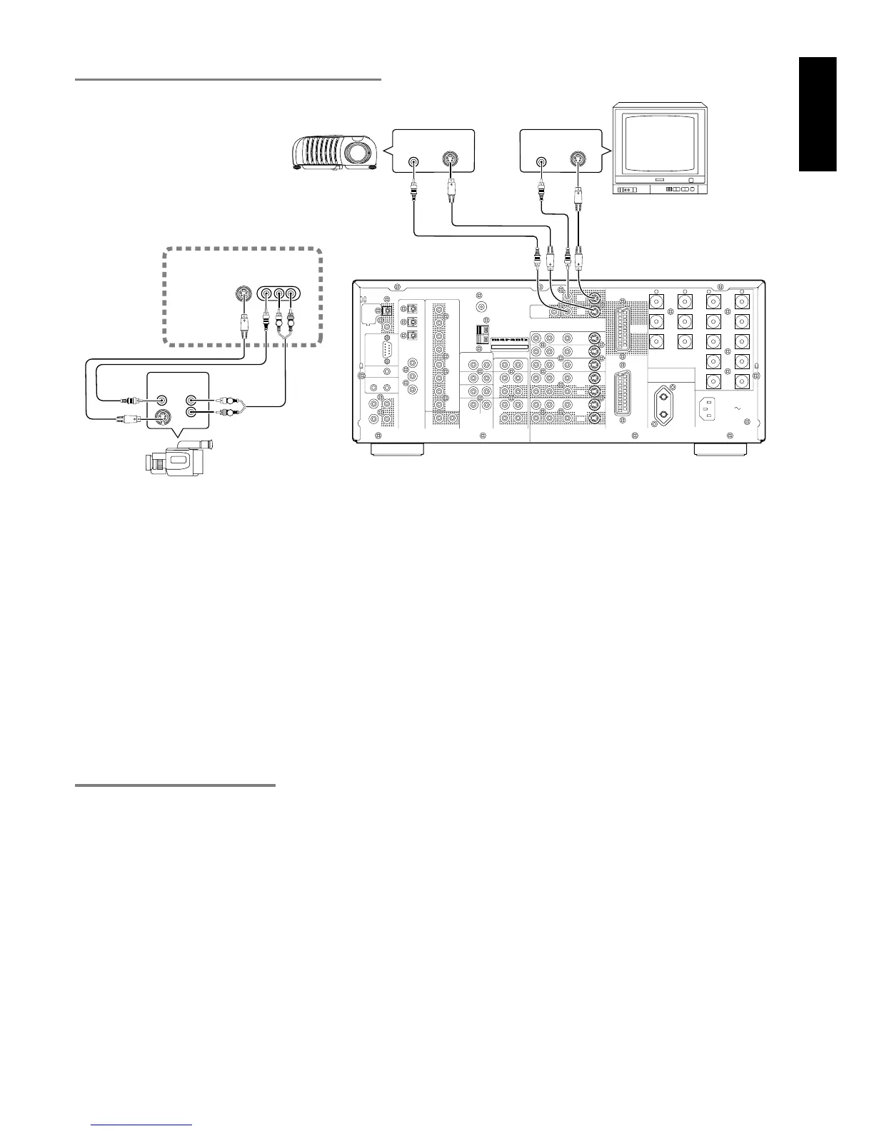
CONNECT TO THE MONITOR AND VIDEO CAMERA
VIDEO, S-VIDEO , SCART JACKS
Notes:
• Be sure to connect the left and right audio channels properly.
Red connectors are for the R (right) channel, and white
connectors are the for L (left) channel.
• Be sure to connect input and output of video signal properly.
• Each type of video jack works independently. Signals input to
the VIDEO (composite) and S-VIDEO jacks or SCART are
output to the corresponding VIDEO (composite) and S-VIDEO
or SCART jacks, respectively.
• This unit has the “TV-AUTO ON/OFF” function to turn ON or
OFF automatically the power by the incoming video signal
from VIDEO jacks.
• You may need to setup the digital audio output format of your
DVD player, or other digital source component. Refer to the
instructions of the each component connected to the digital
input jacks.
• There is no Dolby Digital RF input jack. Please use an external
RF demodulator with Dolby Digital decoder to connect a video
disc player with the Dolby Digital RF output jack to the digital
input jack on this unit.
RC
MULTI
OUT
EXT. IR
OPT
COAX
DIGITAL-OUT
AC IN
OUTIN
SBR
DVD-R
VCR2/
SBL
1
ROOM
MULTI
ROOM
MULTI
RL
SW
LEFT
DC OUT 2
OUT
MULTI VIDEO
ANTENNA
BACK
SURR.
CENTER
C
SR
SL
R
L
OUT
MULTI
RS232C
DC OUT 1
RIGHT
LEFT
CENTER
BACK
SURR.
RIGHT
LEFT
FRONT
LEFT
–
+
SURR.
FRONT
SURR.
RIGHT
DIGITAL-IN
6
5
4
3
2
FRONT
SURR.
7.1CH-IN
R
AM
GND
OUT
OUT
S-VIDEOVIDEO
VCR1
AUDIO
IN
MONI.
1
L
/MD
CD-R
IN
OUT
CD
IN
DVD
L
TAPE
OUT
PRE OUT
IN
SUB.W
R
TV
MONI.
2
LR
DSS
–
+
RC-5
GND
MODEL NO.SR8300
100W
UNSWITCHED
AC OUTLETS
230V 50HZ
DVD IN
SCART/
OUT
MONITOR
6-8 OHMS
SPEAKER SYSTEMS
IN
S-VIDEO
IN
VIDEO
IN
S-VIDEO
IN
VIDEO
RL
R
L
VP8100
VIDEO
OUT
AUDIO
OUT
AUX1 INPUT
VIDEOS-VIDEO
L AUDIO R
L
R
VIDEO PROJECTOR
MONITOR
(FRONT AUX CONNECTIONS)
VIDEO CAMERA