23
Chassis Ground (GND)
The chassis ground terminal is labeled GND.
Power Supply Inputs (3 and 4)
Power input terminals are labeled 3 and 4.
Generator Voltage Sensing Inputs (E1, E2 and E3)
The generator voltage sensing terminals are labeled
E1, E2, and E3. A single-phase sensing connection is
obtained by connecting the phase C sensing input to
terminals E2 and E3.
Exciter Field Output (F+ and F-)
The field output terminals for connection to the gen-
erator exciter field are labeled F+ and F-.
Single Phase Current Sensing Input (CT1 and CT2)
Generator line current is stepped down through a
user-supplied CT on Phase B. Secondary current
(5A) from that transformer is applied to terminals
labeled CT1 and CT2. Consult current transformer
instruction manuals for CT polarity identification and
install per Figure 5-9. See Figure 5-4 and Table 5-1
for terminal assignments.
Three Phase Current Sensing Input
Generator line current is stepped down through
user-supplied CT’s. Secondary current (5A) from
these transformers is applied to the J2 connector.
Consult CT instruction manuals for polarity identifi-
cation and install per Figure 5-8. See Figure 5-5 and
Table 5-2 for terminal assignments. Note: All trans-
formers should have the same CT ratio.
5
Installation
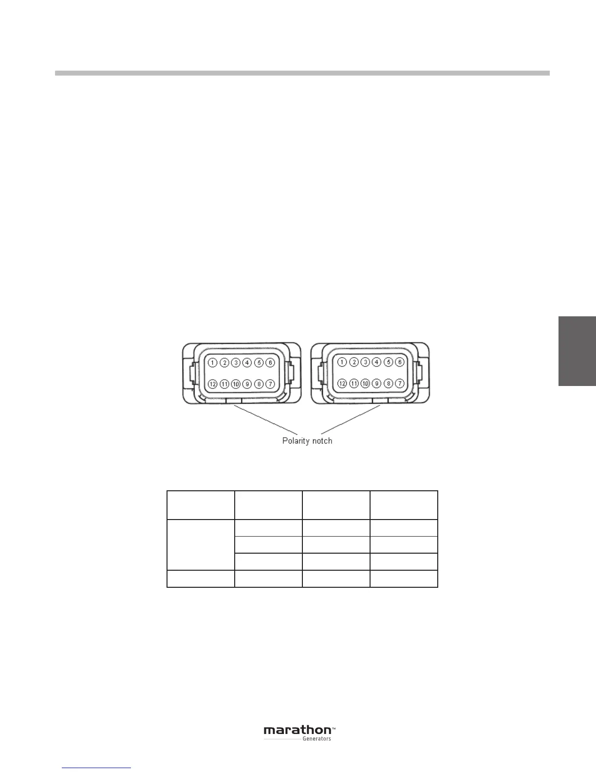
Figure 5-5. System Connectors J2 (left) and J1 (right) Terminal Position
Sensing Phase
CT “X1”
Terminal
CT “X2”
Terminal
3-Phase
A J2-1 J2-12
B J2-2 J2-11
C J2-3 J2-10
1-Phase
B CT1 CT2
Table 5-2. CT Connection Terminals
Note: The CT primaries are aligned such that the “H1” face is facing the generator for typical donut-style CT’s.
GPN046 04-13.indd 23 4/5/13 10:24 AM
 Loading...

