24
UP and DOWN Contact Inputs
Remotesetpointadjustmentmaybeaccomplished
by connecting a SPDT momentary contact switch
to the J1 connector UP and DOWN contacts. To
connect this switch, the common terminal must be
connectedtoJ1-4(CGND).Theothertwoswitchter-
minalsareconnectedtoJ1-2(UP)andJ1-3(DOWN).
Refer to Section 4 – Features and Protection for a
detailed description of the UP and DOWN contact
function.
Parallel Generator Compensation Enable/Disable
(DROOP OFF)
A user can enable or disable the integrated load
sharing function of the regulator by opening or
closing contact between J1-10 (DROOP OFF) and
J1-4(CGND).Closingthecontactdisablesthedroop
function. Refer to Section 4 – Features and Protection
for a detailed description of the Load Sharing
function.
Excitation Enable/Disable (EXCITATION OFF)
A user can enable or disable excitation by opening
orclosingcontactbetweenJ1-11(EXCITATIONOFF)
andJ1-4(CGND).Closingthecontactdisablesexci-
tation. Refer to Section 4 – Features and Protection
for a detailed description of the Excitation Off
function.
Auxiliary Input (AUX_IN (+), AUX_IN (-), and AUX_
LOOP)
This input allows a user to control the regulator with
an auxiliary piece of equipment by connecting a
voltagesourcetoJ1-1(AUXIN+)andJ1-12(AUXIN
-). The regulator can also be configured to accept a
voltage or current to be metered on this input. Refer
to Section 4 – Features and Protection for a detailed
description of the Auxiliary input function.
VAR/PF Enable/Disable (VAR/PF_OFF) (EC+ only)
A user can enable or disable the VAR or PF regula-
tion modes by opening or closing contact between
J1-9 (VAR/PF_ON) and J1-4 (CGND).Opening the
contact enables VAR/PF regulation if the regula-
tion mode was set to VAR or PF in the HMI or
DVRPortal™. Refer to Section 4 – Features and
Protection for a detailed description of the VAR/PF
regulation function.
Note: Operation in VAR or PF modes should only
be enabled when the generator is paralleled with
utility (infinite bus). If the VAR/PF_OFF is open
during power up of the regulator in VAR or PF reg-
ulation modes, a Generator Start Up Fault occurs.
5
Installation
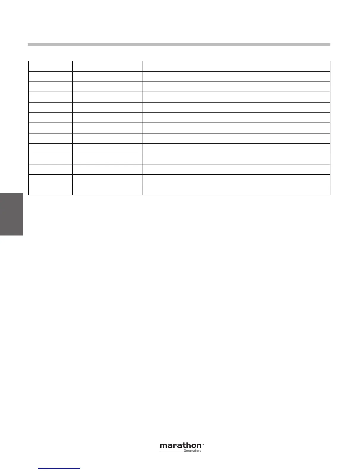
Pin Number Name Description
1 AUX IN (+) Auxiliary input positive
2 UP UP contact input (active low)
3 DOWN DOWNcontactinput(activelow)
4 CGND Input common
5 AUX_LOOP Auxiliarycurrentloopjumper
6 CONTACT1 Contact output
7 CONTACT2 Contact output
8 AUX_LOOP Auxiliarycurrentloopjumper
9 VAR/PF_OFF VAR/PFregulationdisablecontact(activelow,EC+only)
10 DROOP_OFF Droop disable contact input (active low)
11 EXCITATION_OFF Excitation disable contact input (active low)
12 AUX IN (-) Auxiliary input negative
Table 5-3. Connector J1 System Connections
GPN046 04-13.indd 24 4/5/13 10:24 AM
 Loading...

