25
Contact Output (CONTACT1 and CONTACT2)
The output contact may be accessed at connec-
tor J1, via terminals J1-6 (CONTACT1) and J1-7
(CONTACT2). The relay output is normally open and
closes when the regulator goes into a fault condition.
5
Installation
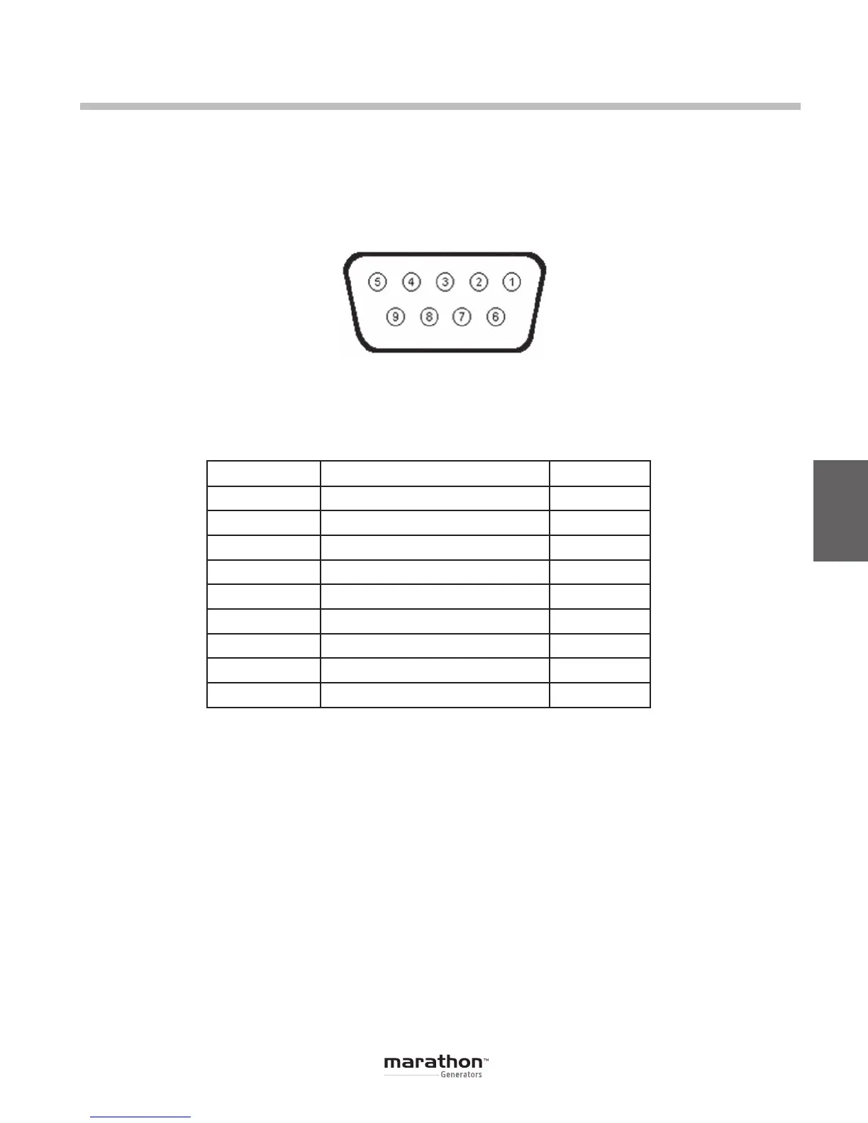
Figure 5-6. RS-232 Communication Port Terminal Positions
Pin Number Function Name
1 N/C
2 Receive Data RXD
3 Transmit Data TXD
4 Data Terminal Ready DTR
5 Signal Ground GND
6 Data Set Ready DSR
7 Ready To Send RTS
8 N/C
9 N/C
Table 5-4. RS-232 Communication Port Pin Functions
Note: If serial port does not support DTR and RTS
functions, then these lines must be connected to
serial port positive supply voltage of Data Terminal
Equipment.
Serial Communication Port
The RS-232 port on the rear panel uses a DB-9
female connector. Figure 5-6 and Table 5-4 illustrate
the pin assignments of the communication port from
the perspective of the PC. A standard communica-
tion cable terminated with a DB-9 male connector is
used for PC interface with the DVR
®
. Note: Do not
use a “cross-over” or “null-modem” cable.
GPN046 04-13.indd 25 4/5/13 10:24 AM
 Loading...

