26
5
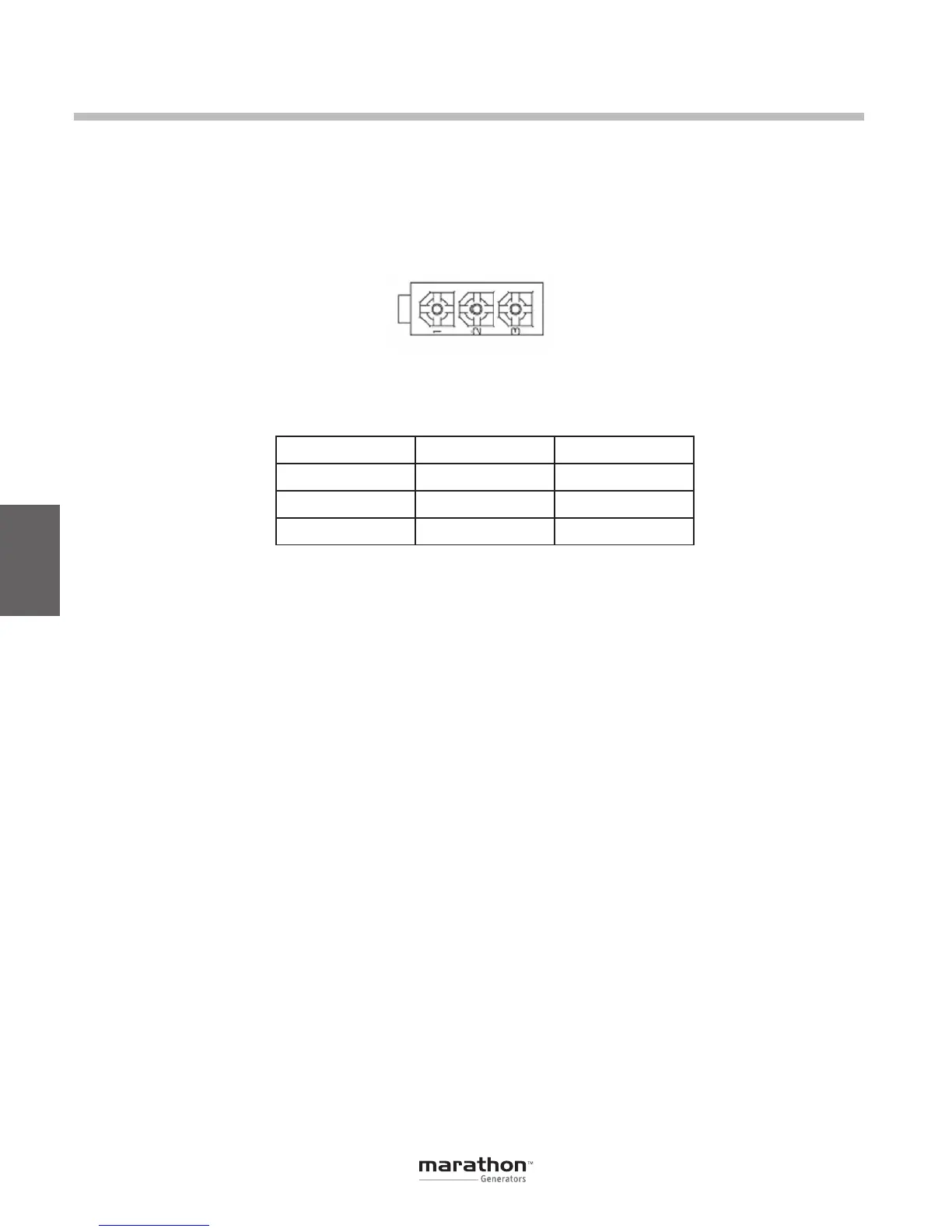
CAN J1939 Communication Port (J3)
TheCAN portonthe rearpaneluses anAMP/Tyco
Mini Mat-N-Lok connector. Figure 5-7 illustrates
the pin assignments of the CAN port and Table 5-5
identifies the pin functions of the CAN port.
Installation
Figure 5-7. Connector J3 CAN Port Pin Assignment
Table 5-5. Connector J3 CAN Port Pin Functions
Pin Number Function Name
1 CAN High CAN_H
2 CAN Low CAN_L
3 CAN Ground CAN_GND
DVR
®
Connections for Typical Applications
Figures 5-8 through 5-11 illustrate typical applica-
tions using the DVR
®
.
• Figure 5-8 shows an application where
the regulator is connected for three-phase
voltage sensing and three-phase current
sensing.
• Figure 5-9 shows an application where
the regulator is connected for three-phase
voltage sensing and single-phase current
sensing.
• Figure5-10showsanapplicationwherethe
regulator is connected for with single-phase
voltage sensing and single-phase current
sensing.
• Figure 5-11 illustrates an application with a
single-phase generator.
Figures 5-12 and 5-13 illustrate how the regulators
can be interconnected for use in Cross-Current
(ReactiveDifferential)applications.Whenoperating
in Cross-Current mode, attention must be paid to
the use of the burden resistor shown in Figures 5-12
and 5-13. The burden resistor should have a value of
approximately 10 times the cross current loop resis-
tance for proper differential operation. The value
of 0.1 ohm is a suggested value. The volt-ampere
(VA) capacity of the paralleling current transformers
should be considered when sizing the burden resis-
tor.
GPN046 04-13.indd 26 4/5/13 10:24 AM
 Loading...

