30
5
FIELD
OUTPUT
INPUT
POWER
CT-B
SENSING
VOLTAGE
F-
4
3
F+
GND
CT1
CT2
-1
-12-2-11E1 E2
E3
J2
-10-3
-11-2
-3 -10-9
-4
-6
-7
-1 -12
-5
-8
CT-A CT-B
CT-C
EXC
OFF
UP
DOWN
DROOP
OFF
VAR/PF
OFF
CGND
AL1AL2
AUX
IN+
AUX
IN-
AUX
CURRENT
LOOP
J1
-1
-2
-3
CAN
HIGH
CAN
LOW
CAN
GND
J3
DVR2000E+ / EC+
GEN
PMG
S3
S1
QUICK CONNECT TERMINALS
CAN
Network
9
EXCITER
L1
N
L2
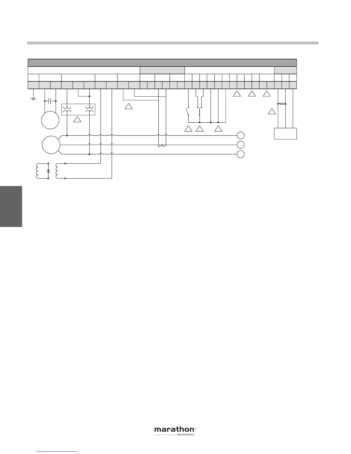
NOTES:
1. Excitation enabled when switch (S3) is open and disabled when switch is closed.
2. SPDT spring return to center-OFF position type switch (S1) for remote set point adjust.
3. J1-10 (DROOP_OFF) and J1-9 (VAR/PF_OFF) (if DVR2000EC+) are shorted to J1-4 (CGND) to
disable droop and VAR/PF control modes.
4. Normally-open contact closes in a fault condition.
5. Analog signal input when Auxiliary is configured for control or metering.
6. Should be shorted when Auxiliary is configured for 4-20 mA control or metering.
7. Sensing potential transformer is required if generator output voltage exceeds 600 Volts.
8. Phase B current transformer (CT-B) secondary may be connected to either quick-connect
terminals CT1 and CT2 or J2-2 and J2-11.
9. 120 ohm 0.25 watt resistor required if DVR is a terminal device on CAN backbone.
10. S1, S3 and transfomers supplied by others.
3
21
8
4
5
6
7
7.5 uF
370 Vac
Figure 4-10. Typical Connections with a Single-Phase Generator
120
Ohm
Installation
Figure 5-11. Typical Connections to a Single-Phase Generator
GPN046 04-13.indd 30 4/5/13 10:24 AM