TS 910 TRANSFER SWITCH
PM140 REV 2 14/01/23 4 Thomson Power Systems
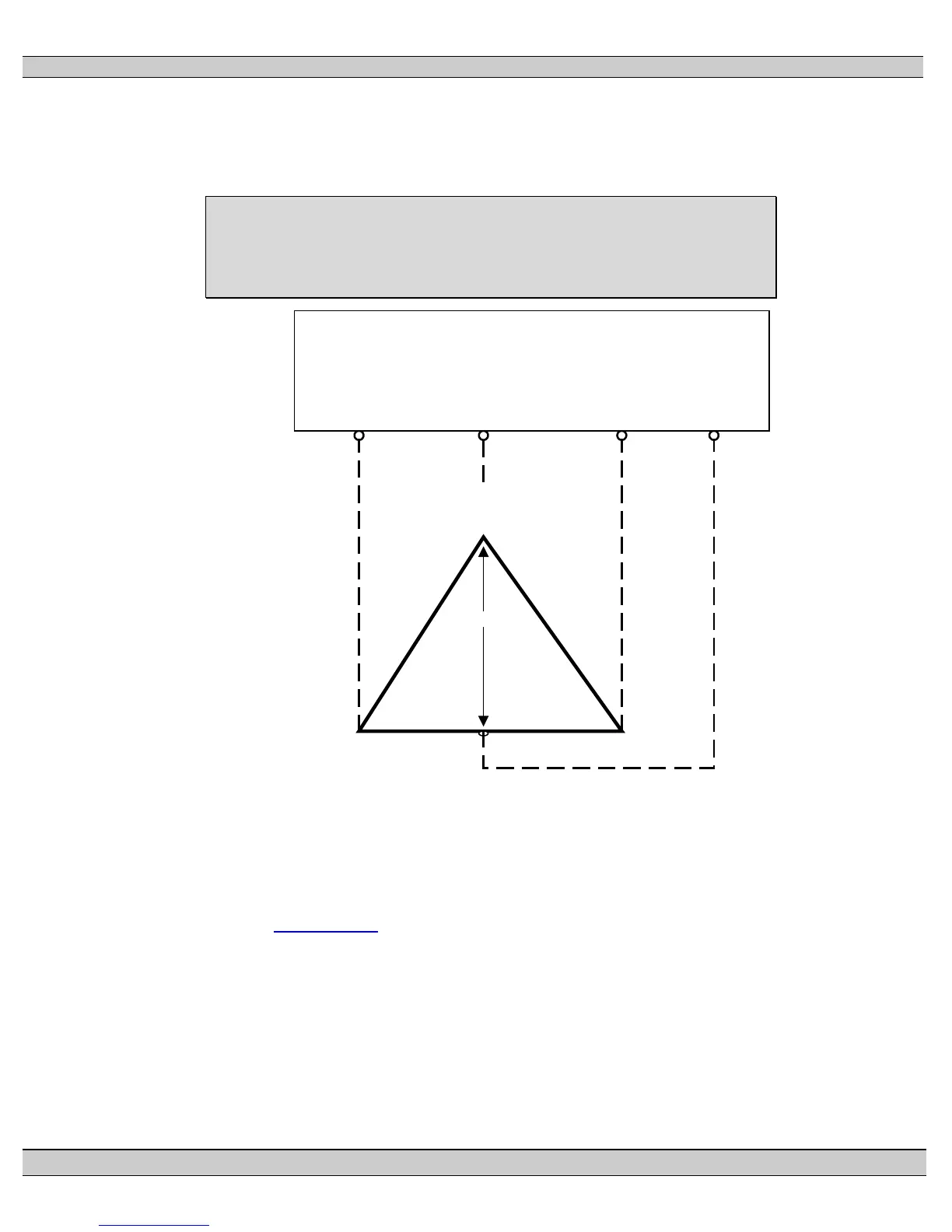
colored Orange per “NEC 384-3(e)” identified as the leg with highest potential with reference
to ground). This will ensure the ATS control power that is internally connected between
phase A and neutral is maintained at 120VAC. Refer to figure below for further details.
WARNING
Failure to match correct system phasing will result in serious
damage to the Transfer Switch.
208V
B
(Orange)
(High Leg)
C
(Yellow)
A
(Red)
N
(White)
PH A
(UA)
Automatic Transfer
Switch (Utility Supply)
PH B
(UB)
PH C
(UC)
Neural
(N)
120V 120V
240V 240V
Note: For correct voltage sensing operation on High Leg Delta systems, the TSC 9
controller must have the configuration jumpers set at “240V” and “3PH” settings.
Refer to Section 18.15 TSC 9 CONFIGURATION INSTRUCTIONS of this manual
for further details.
3.4.5 Control Wiring
All control wiring for engine start, load shed, alarm and remote test must be installed
in separate conduits from all power cabling and must utilize suitably sized conduits
per NEC requirements. All control wiring shall be sized for minimum #14 AWG.